QA BEAMCHECKER™ PLUS 36
Dynamic 5 Channel Room
OCC Output Constancy (Center) Out of Tolerance
OCT Output Constancy (Top) Out of Tolerance
OCb Output Constancy (Bottom) Out of Tolerance
OCL Output Constancy (Left) Out of Tolerance
OCR Output Constancy (Right) Out of Tolerance
TomoTherapy System Room - Static Mode
ENC Energy Constancy Out of Tolerance
LPC Lateral Profile Constancy Out of Tolerance
OCC Output Constancy (Center) Out of Tolerance
TomoTherapy System Room - Dynamic Mode
OCC Output Constancy (Center) Out of Tolerance
OCL Output Constancy (Left) Out of Tolerance
OCR Output Constancy (Right) Out of Tolerance
If one or more of these faults occur, follow the QA protocols defined by the facility to
determine the next course of action.
7.5 Measurement with Real-Time Operation Mode
Select the appropriate section below based on application: Static 5 Channel (traditional linear
accelerator photon/electron measurements), Dynamic 5 Channel (IMAT, VMAT, or dynamic
wedge measurements) or TomoTherapy System (static or dynamic exposure).
NOTE: A Bluetooth Adapter Kit (REF 70504) is an available option allowing
wireless communication from the PC to the QA BeamChecker Plus in place
of a wired serial connection. See page 53 for more details.
Static 5 Channel Room
1. Choose whether measuring photons or electrons. If using electrons, ensure a 20 x 20 cm
electron cone is attached to the accelerator.
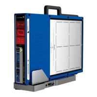
2. Place the QA BeamChecker Plus on the treatment couch ensuring it is flipped to the proper
side, Photon or Electron, as indicated by the large white field labels on both sides of the device.
3. Position the QA BeamChecker Plus at 100 cm SSD with a field size of 20 x 20 cm. Align the
unit to the center of the field using the QA BeamChecker Plus fiducials and the room
alignment lasers.
4. Connect the QA BeamChecker Plus to the PC as shown in Figure 5 and exit the vault.
5. On the PC connected to the QA BeamChecker Plus, launch the QA BeamChecker Plus
Communication Software.
NOTE: The QA BeamChecker Plus should automatically turn on when the communication
software is launched.