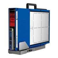
QA BEAMCHECKER™ PLUS 8
while the “electron” side provides 1.5 cm. To switch sides, the unit is simply flipped over, and
the MODE / PLAN button on the front of the unit is pushed to indicate the change and to
invert the display. No additional buildup or trips into the treatment vault are typically required.
In daily use for TomoTherapy or other rotational units, only the photon side is used. The
following are evaluated for TomoTherapy mode: laser alignment (both fixed and moving),
static output constancy, static energy constancy, lateral profile constancy, and dynamic output
constancy.
Following an exposure, the QA BeamChecker Plus identifies the energy of the beam that was
just used. It then applies this reading to look up the baseline parameters for that beam energy
and compares them with the present readings. Daily measurements falling within the
physicist-selected acceptance parameters (known as Action Levels) result in a green light
displaying on the front panel of the device for about 10 seconds, followed by the unit re-
arming itself for the next measurement. All data is stored on the QA BeamChecker Plus for
later downloading. Measurements outside acceptance parameters cause a red light to flash,
an audio alert to sound, and require the RESET button to be pushed on the front of the
instrument to continue. Additional information is also presented on the large alphanumeric
display on the front of the unit.
For rotational treatment machines or for dynamic beam delivery, such as enhanced dynamic
wedge, the core functionality is very similar, however instead of selecting an energy to deliver,
a plan is configured. This plan could be a particular energy, wedge angle, and jaw width (in the
case of a TomoTherapy system) or any other unique identifier. In typical use for rotational
delivery such as RapidArc™, first a CT image of the QA BeamChecker Plus must be acquired in
order to contour its internal ion chambers. Using the image and its contours, a treatment plan
is developed and delivered to the unit as a baseline measurement. Subsequent exposures
compare the total composite dose delivered to each chamber to their baseline value, with any
deviation signaling a problem with the beam delivery. Potential problems tested could
include gantry rotation, dose rate, and/or delivery position.
About one month’s worth of data can be stored on the QA BeamChecker Plus before
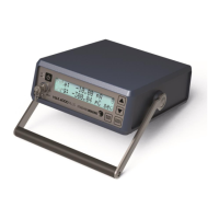
downloading is required, although downloading may be done at any time. The Power/Data
Cradle provides the link to the computer’s RS-232 port, and the included software makes
downloading and trending the data quick and easy. The simple four-tab interface guides the
physicist through all the steps needed to evaluate data. Values for flatness, symmetry, and
constancy are graphically displayed for analysis and review. Data can be viewed in graph or
table form, and can easily be printed for archiving, if desired.
New memory management and diagnostic tools have been added in version 2.3 of the QA
BeamChecker Plus, including:
• Improved clock function check on unit startup.
• Memory wear leveling: Measurement data better balanced across the entire memory
footprint.
• CRC check and auto-correct from memory mirror on unit startup.
• Stand-alone diagnostic tool for improved Standard Imaging Support.