9. Use cable ties to restrain the cables to the pillar.
10. At the bottom of the control box, connect the RO1 power and data cables to the control box, as
well as the USB cable. Connect the IEC (power) cable and lock it with the clip.
11. Press the power button on the top of the control box to start the RO1.
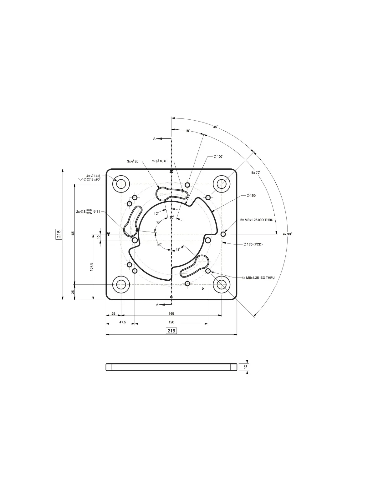
3.4.4 Mounting Base Diagram:
22