02.11
Strapex SMA 20
53
11
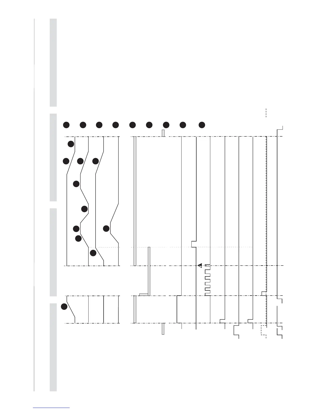
ABLAUFDIAGRAMM FUNCTIONAL DIAGRAM SCHÉMA FONCTIONNEL SCHEMA FUNZIONALE
0
0
360
0
32
0
32
0
1
2
3
4
5
6
7
8
8
8
9
Fusschalter Band-vor
Foot switch strap forward
Interrupteur pédale avance de la bande
Interrutore a pedale avanzamento nastro
S5 =
K1
K3
K4
Y1
Y2
Y3
B1
B2
B3
B4
S2
S5
K2
S3
S1
Klemmer, rechts
Clamp, right
Pince, droite
Morsetto destro
Klemmer, Mitte
Clamp, center
Pince, centre
Morsetto centrake
Klemmer, links
Clamp, left
Pince, gauche
Morsetto sinistro
Heizelement
Heating element
Elément de chauffage
Elemento riscaldante
Aggregat
Aggregat
Aggregat
Aggregato
Rückzug-Spannen
Take-up tensioning
Retour tendre
Allentamento tensione
Band vor
Strap forward
Avance de la bande
Avanzamento mastro
Aggregat
Aggregat
Aggregat
Aggregato
Bandspannung lösen
Strap tension loosen
Desserrer tension de bande
Allentamento nastro
Umschalten auf Aggregat
ggregato
Umreifung auslösen
Strapping start
Cerclage départ
Inizio reggiatura
Impulstaste Band vor
Impuls button strap forward
Bouton poussoir de bande
Pulsante avanzamento nastro
Impulstaste Reset
Impuls button reset
Bouton poussoir reset
Pulsante ripristino
Fusschalter Umreifung auslösen
Foot switch strapping start
Interrupteur pédale cerclage départ
Interruttore a pedale
Motor start
Motor start
Moteur départ
Avviamento motore
Klemmer, rechts
Clamp, right
Pince, droite
Morsetto destro
Band geklemmt
Strap clamped
Serre de la bande
Nastro incastrato
1
Klemmer, links
Clamp, left
Pince, gauche
Morsetto sinestro
Band geklemmt
Strap clamped
Serre de la bande
Nastro incastrato
2
Klemmer, Mitte
Clamp, center
Pince, centre
Morsetto centrale
Band wird abgeschnitten
Strap cut-off
Couteuau de la bande
Recisione nastro
3
Bandtrennung zurück
Strap separator back
Separation de bande retour
Ritorno separatore nastro
Heizelement zwischen den Bändern
Heating element between the straps
Element de chauffage
Elemento riscaldante verso l'alto
4
Bander werden erwärmt
Straps will be heated
La bande sur la chauffage
Nastri in riscaldamento
5
Klemmer, Mitte nach unten
Clamp, center downward
Pince, centre en base
Morsetto centrale verso il baso
Heizelement in Ausgangsstellung
Heating element in base position
Element de chauffage position de base
Elemento riscaldante verso l'alto
6
Klemmer, Mitte nach oben
Clamp, center upward
Pince, centre monter
Morsetto centrale verso l'alto
Bänder werden verschweisst und gepress
Straps welded and pressed
La bande soudure et pression
Nastri vengono saldati e pressati
Alle drei Klemmer zurück
All tree clamps back
Tout pinces retour
I tre morsetti indietro
Schieberplatte und Bandtrennung
zurück in 0
0
Stellung
Sliding platte and strap separator
back in 0
0
position
Plaque du curseur et séparateur
de la bande retour en 0
0
position
Placca scorrevole e separatore
nastro indietro in pos. 0
0
Ausgänge Output Sorties Uscite
Eingänge Input Entrées Entrate
Elektromagnet Kupplungen
Electromagnetic clutches
Embrayages électromagnétique
Frizione elettromagnetica
Y =
Kurvenscheibe
Cam
Disque à came
Camma a disco
K =
Tasten/Schalter
Button/Switch
Touche/Interrupteur
Pulsanti/interruttori
S =
Mikroschalter
Limit switches
Microinterrupteur
Microinterruttore
B =
7
8
9
Klemmer, Mitte nach oben
Clamp, center upward
Pince, centre monter
Morsetto centrale verso l'alto