www.stryker.com 6390-009-002 REV D 77
Service
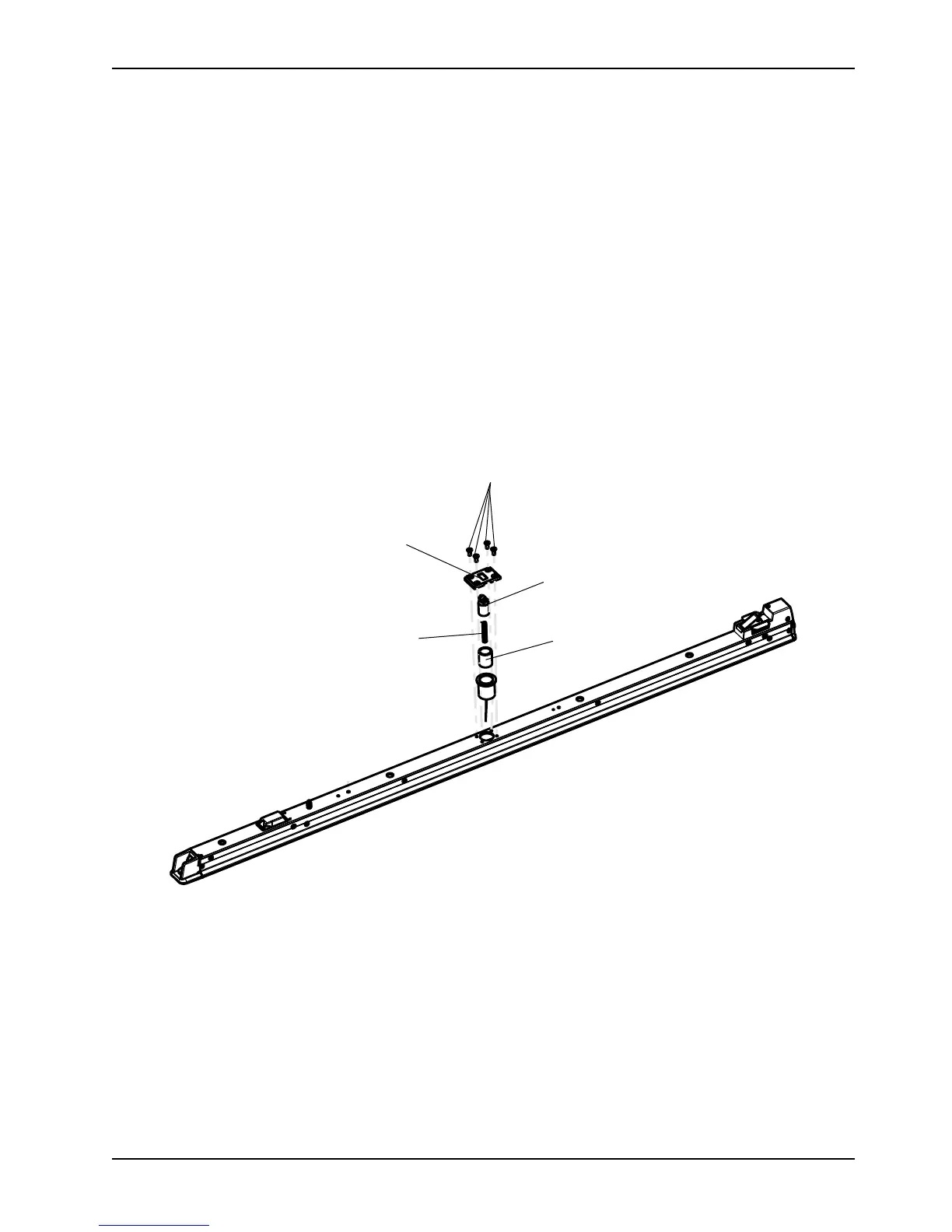
Transfer lock bearing removal and replacement (Continued)
3. Using a 5/32'' hex wrench, remove the four flat head cap screws (A) that secure the transfer lock cap (B) to the
anchor extrusion (Figure 47 on page 77).
4. Remove the transfer lock cap (B) (Figure 47 on page 77).
5. Remove the transfer lock pin assembly (C), compression spring (D), and bronze bearing (E) from the anchor
extrusion (Figure 47 on page 77). Discard the bronze bearing.
6. Clean the transfer lock pin assembly (C) and compression spring (D) thoroughly (Figure 47 on page 77).
7. Install the supplied bronze bearing (D), compression spring (D), and transfer lock pin assembly (C) into the anchor
extrusion (Figure 47 on page 77).
Note:
Prior to reinstallation, grease the transfer lock pin assembly with molybdenum disulfide lubricant (6390-001-263).
8. Using a 5/32'' hex wrench, reinstall the four flat head cap screws that secure that transfer lock cap (B) to the
anchor extrusion. Start each screw first and then tighten all four screws.
9. Reinstall the transfer. See Transfer removal on page 37.
10. Reinstall the trolley. See Trolley removal on page 37.
Figure 47: Transfer lock bearing removal and replacement
 Loading...