STRYKER MEDICAL/BERTEC MÉDICAL APPENDICES A - 3
SCHÉMA DE BRANCHEMENT
Commandes patient
Assembler les fils
dans les connecteurs
comme ceci;
Rouge = #1 / Red = #1 / Rojo = no 1
Brun = #3 / Brown = #3 / Marron = no 3
Vert = #4 / Green = #4 / Verde = no 4
Bleu = #6 / Blue = #6 / Azul = no 6
Orange = #9 / Orange = #9 / Naranja = no 9
Blanc = #7 / White = #7 / Blanco = no 7
Noir = #8 / Black = #8 / Negro = no 8
Pied monte / Feet up / Sube pie
Commun / Ground / Tierra
Pied descend / Feet down / Baja pie
Centre monte / Centre up / Sube centro
Centre descend / Centre down / Baja centro
Tête monte / Head up / Sube cabecera
Tête descend / Head down / Baja cabecera
Nursing control centre
Moteur de tête / Head motor / Motor de la cabecera
Moteur de pied / Foot motor / Motor del pie
Moteur de lit
Bed motor
Motor de la cama
Moteur de pied
Foot motor
Motor del pie
120V
Noir/Black/Negro
Blanc/White/Blanco
Rouge/Red/Rojo
Vide/Empty/ Vacio
Auto-CPR switchs (J2 pos. 2,3) /
02
Moteur lit/Bed motor/Motor de la cama
03 Moteur tête/Head motor/Motor de la cabecera
05
Commande infir./Nursing control/Controles del paciente
06
Veilleuse/Nigth light/Luz nocturna(option/opción)
07 Fiche qualitée hôpital/Hospital grade plug/Enchufe para hospitales
09
Commandes patient/Patient controls/Controles paciente(option,opción)
Fil commande patient/Patient control cable/Cable control. del paciente(option,opción)
20
19
Fil interrupteur/Interruptor cable/Cable interruptor(option,opción)
18
01
Moteur pied/Foot motor/Motor del pie
Patient Controls
CONNECTION DIAGRAM
Tableau de commande
Interrupteurs Auto-CPR(J2 pos. 2,3)/
Blanc/White/Blanco
Noir/Black/Negro
Vide/Empty/ Vacio
Rouge/Red/Rojo
Assemble wires
as shown;
QE71-0369
1
1
2
1
1
1
1
1
1
DIAGRAMA DE CONNEXIÓN
Connectar los cables
según al diagrama;
Interruptor automático del
Centro de control del personal
Controles del paciente
Patient Controls
Commandes patient
Carte de contrôle/PC Board/Tarjeta de circuitos impresos04
1
120V
Moteur de tête
Head motor
Motor de la cabacera
120V
Noir/Black/Negro
Blanc/White/BlancoRouge/Red/Rojo
Vide/Empty/ Vacio
08
Fil en "Y" (7 pins)/"Y" cable (7 pins)/cable en "y" de 7 espigas
1
Contour positioning switch (J2 pos. 4,5,6,7) /
Interruptor de contorno autopostura(J2 pos. 4,5,6,7)
Interrupteurs Auto-contour 1 et 2(J2 pos. 4,5,6,7)/
somier de cabecera(J2 pos. 2,3)
17
1
16
Fil interrupteur CPR/CPR cable/Cable automático del somier de cabecera(option,opción)
2
Moteur de lit / Bed motor / Motor de la cama
Fil d'alimention/Power cable/Cable de alimentación(option,opción)10
1
Inter. auto-contour/Contour positioning switch/Inter. contorno autopostura (option,opción)
13
14
15
2
1
1
117
FL13E-_ _ _ _
Cavalier/Jumper/ Puente 1
Transformateur /
Transformer /
Transformador
Prise auxilière/Auxilary socket/Enchufe auxiliar(option,opción)
Transformateur/Transformer/Transformador(option,opción)
Interrupteur CRP/CPR switch/Inter. automático del somier decabecera(option,opción)12
2
Disjoncteur 5A/Breaker 5A/Disyuntor 5A(option,opción)11 1
Fiche 120V/120V Plug/
Enchufe 120V
ou/or/o
100V/200V/
220V/240V
120V
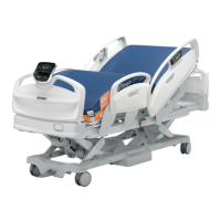
Lit modèle
Bed model
Cama modelo
Prise veilleuse/Night light socket/Enchufe para luz nocturna
Qté
QtéNo. No.
Vivant/Line/Línea viva
Neutre/Neutral/Línea neatra
Cavalier / Jumper / Puente
(W1 pos.1,2)
 Loading...