81307063I
EN
44
Digital Output 1 Logic IO function
Output Function IO signal 1
[Logic IO] [True OR]
Normaly State IO number 28
[Normaly Open (NO)] IO signal 2
[True OR]
IO number 29
IO signal 3
[True OR]
IO number 30
IO signal 4
Esc
TheresultwillbethatDO1willbeactivatedifanyofthealarmsfortemperaturearetriggered.
4.2 Digital output type: data reg. setpoint
WiththeDigitalOutputType“Data reg. Setpoint”asetpointcanbetiedtoanyanalogsignal,internalorexter-
nal.ByusingtheregistersdenedintheModbusmanualandenteringtheminthefunctionasintheexample
below,youcanachievethisfunction.
Example Wehaveasulphuricgasmonitoringdeviceconnectedtoananaloginputsignal.WeuseA.IN5forthesulphuric
meter.InthiscasewewantaswitchonDO1whentheconcentrationofgasisorabove10.0ppm.Wealso
wanttheoutputsignaltoswitchbackat1.0ppm(ahysteresisof9ppm).Thisdigitaloutput1controlsafan
which evacuates the gas from the station.
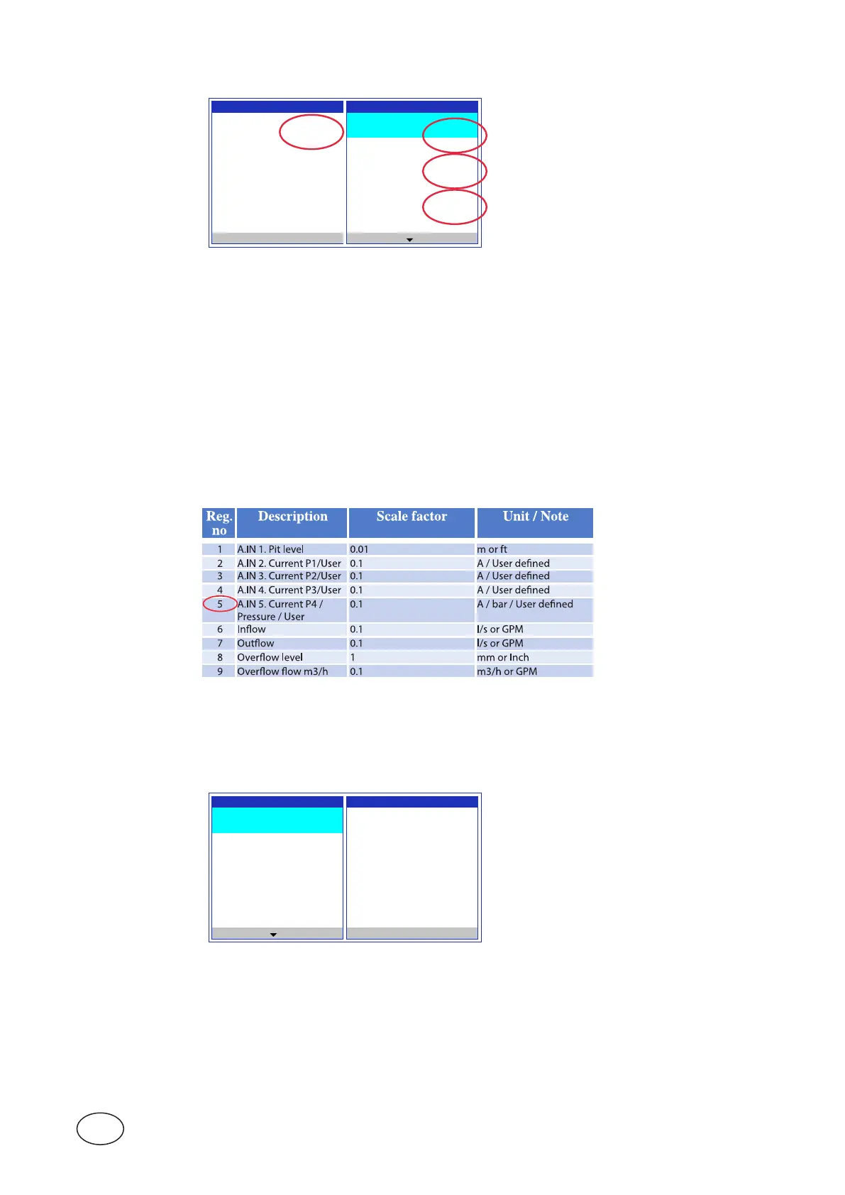
NOTE! According to Comli/Modbus reference manual(p/n81307126)wendthattheregisterforanaloginput5istoread
on register 5;seegure4-2below.Wenoteaswellthatthescalefactoris0.1(i.e. the value in reg.5 is multi-
plied by 0.1 to get actual value in engineering units).
Figure 4-2 AbovetableisanextractfromtheComli/ModbusmanualforPC441–
Analog inputs/Output in engineering units.
ThefunctionisconguredinthemenuofCA511asfollows:UnderSettings / Digital outputs / PC 441 Main (or
CA 781 Exp.-) Module / Digital output 1 to [Data reg. setpoint] according to picture below.
Andthentypeinthesetpointvalue100forONstateandthevalue10forOFFstate
Digital Output 1 Digital Output 1
Output Function Data Register
[Data reg. Setpoint] 5
Normaly State Setpoint ON
[Normaly Open (NO)] 100
Setpoint OFF
10
Setpoint Delay
Esc
The Setpoint ON=100 correspond to the value of 10 engineering units and
Setpoint OFF=10 correspond to 1.
AboveisanexampleofhowtogetananalogsensorsignaltochangestateonaDigital Output signal via Data
reg. setpoint function.