81307063I
EN
4
8.Sulzerwirelessmodem
Max 1 unit per system
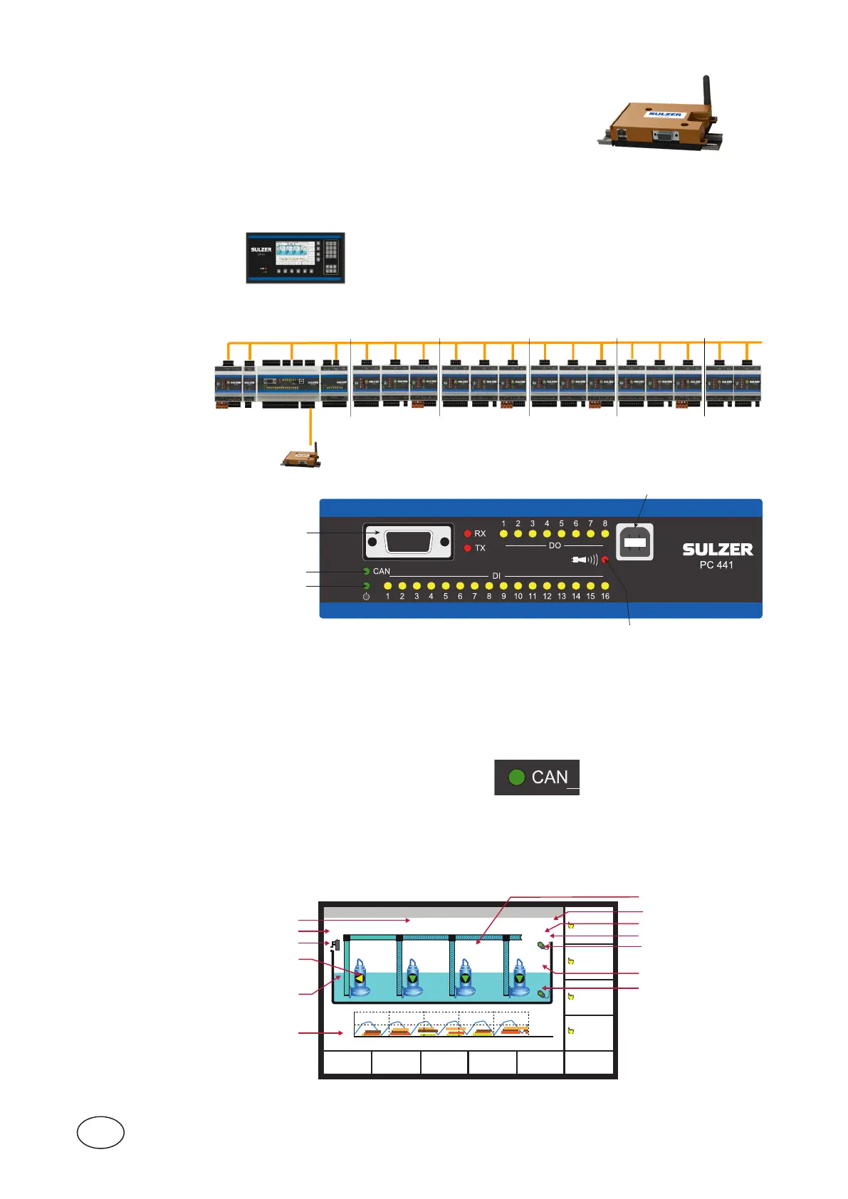
Thebaseunit,PC441,communicateswiththeextensionmodulesviaCANcommunication.
Seetheinstallationguidehowtoconnecttheextensionmodules.Afullyextendedsystemcanlooklikethis:
8.
Modem
Figure 1-1
RS-232 port for a computer
(service port or com echo see 3.8.5)
Power indicator
Field bus indicator
Alarm indicator
USB (service port)
Agreenlampattheveryleftindicatesthattheunitispowered(eitherbatteryormains).
Theredalarmindicatorwillblinkwheneverthereisanunacknowledgedalarm.
1.1 Field bus status indicator
Pumpcontroller,operatorpanelandmonitoringmodulescommunicatesviaaCANbus.
Fixedgreenlight=connectedOK
Flashinggreenlight=searchingformodules
Flashingredlight=InvalidIDsetonmodule
1.2 CA 511 operator panel
Younavigatethemenusbythearrowbuttons.PresseithertheUp or Down arrow button to switch to the menu
view.YouconrmanoperationwiththeEnterbutton,oracknowledgeanalarm.PressingtheEscape button
will cancel the current operation.
Figure 1-2
0 A
1.30 m
0.50 m
1.50 m
0.55 m
1.70 m
0.60 m
1.90 m
0.65 m
352.5 A 353.8 A 354.1 A
1.55 m
1827 l/s
3.8 bar
MAIN STATUS SETTING TREND ALARM ACKN.
PUMP 4
PUMP 3
PUMP 2
PUMP 1
2019.01.23 05:56:19 Low level
980.3 l/s
m
P3 P4
P1 P2
3
0
07:25:58 07:28:10 07:30:26
0.15 kWh/m3
Height of water in pit
Overflow detector
Inward flow to pit
Trend curve
Shows operation
(animated)
Height of water
(animated)
High-level float sensor
Low-level float sensor
Outward flow from pit
Back-pressure
Current consumption for pump
Total pump efficiency
Thedisplayanditsinformationeldsinthedefaulttop-levelview.
Upto4pumpsvia16Din,16Dout,5Ain,4Aout
3 moisture and 5 temperature inputs per pump
Temp L2 & L3
-> CA 511
Station
P1 P2 P3 P4 P1 P3
P2 P4