81307063I
EN
33
3.2.3 System curve
Apumpisalmostalwaysseeninasystemofpipelinesandvalves.Thesegivelossesthatthepumpmust
overcomeforaspecicow.Withthesystemcurveisthesumofthestaticheightandpipelinesystemlosses
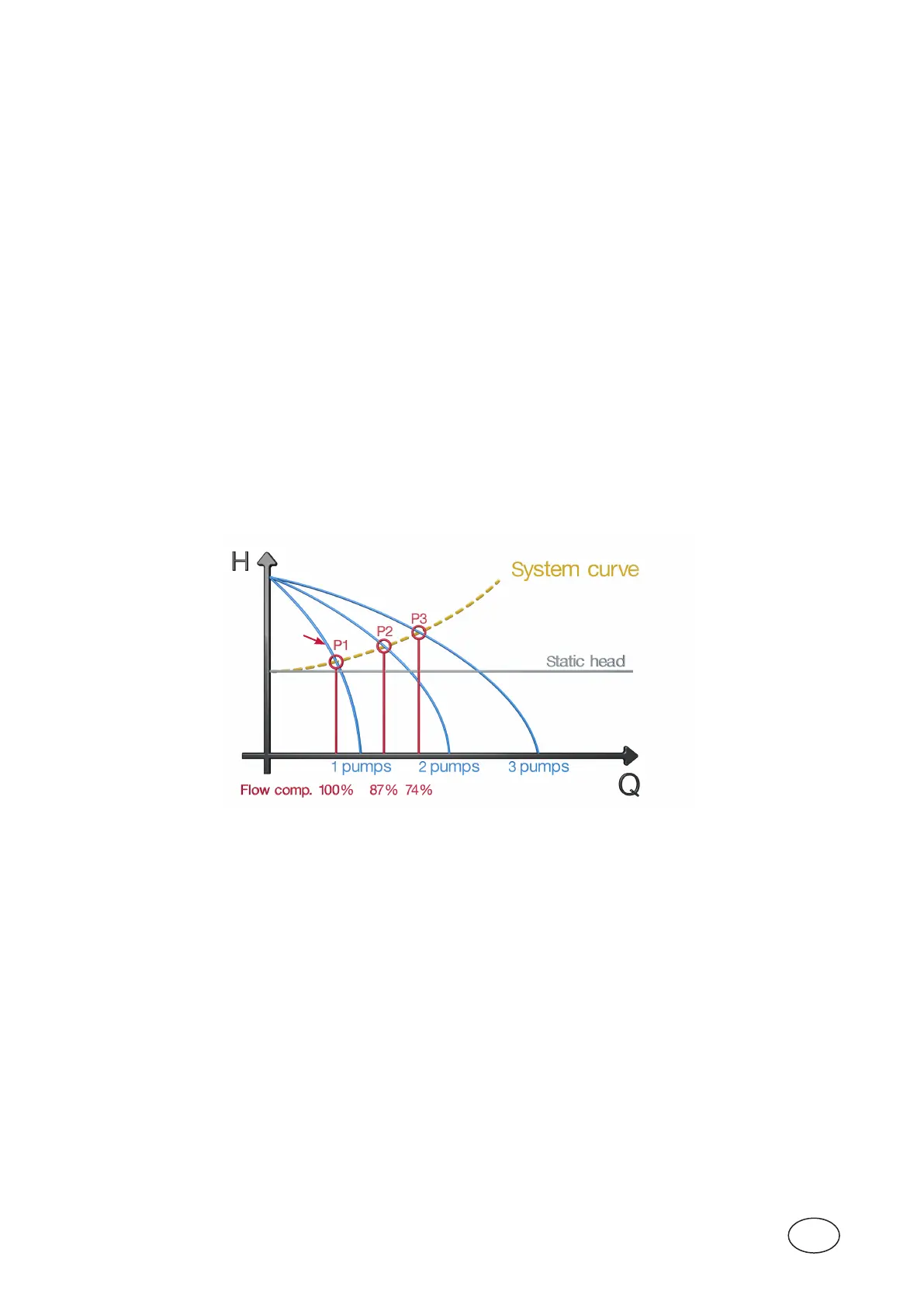
ataspecicow(total head).Youmaythinkthatiftwoequalpumpsparallelcoupledarerunningtheoutow
willincreasebyafactorof2.Sometimesitturnsout,however,thattheoutowwillonlyincreasealittle.This
isbecausethepipelinelossesincreasewithincreasedowandthusthetotalliftheight.Ifyoudonotcom-
pensateforthis,thecalculationoftheoutputowandpumpedvolumewillbeincorrectinthecaseofseveral
pumpsrunning.Thisisespeciallytruewhenwehavegreatpressurelossesinthepipeinrelationtothestatic
heightPC441hastwodierentwaystocompensateforthis.
1. OnewayistomanuallysettheparametersinthemenuFlow compensation under menu Stationow>
Meas. parameters.
Speciesthefactorsasapercentageofthepumpcapacitymeasuredwhentheonepumpisrunning
(1pumprunning=100%).Setfactorsfor2,3and4pumpsrunning.SettheparametersinthemenuSystem
curvetozero,whichturnsoautomaticcalculation(see2below).
Itcanbediculttoestimatehowmuchcapacitydecreasesatthedierentoperationalcases.
2. Enterthedutypointofthesystemcurveforapump.
In menu System curve under Stationow>Meas.parameterssetthedutypointforapump.
Systemcurveanddutypointcanbecalculatedmanuallyorbyusinganycalculationprogramssuchas
ABSELPROfromSulzer.
Set the static and total lifting height (static and total head)atthespecicow.PC441canusethistocalcu-
latecompensationfactorsfortheoutowwhenmorethanonepumpisrunning.
After calculation menu Flow compensation shows the calculated factors.
NOTE! Forthistowork,eachpumpmusthavetheirpumpcurveenteredinthefollowingmenu(s),Menu pump 1-4 >
Pump curve.
Figure 3-7 Flow compensation 3 pumps.
Enterthepoint“A”tothesystemcurvemenus.
NOTE! Theeasiestandmostreliablewaytoobtainthesystemcurveandtheoperatingpointsforsoloandmultiple
pumpsoperatingatvaryingstaticheadistouseacombinedpipeworklossesandpumpselectionsimulation
softwarepackage,e.g.SulzerABSEL.Ifthesystemcurveand(ifapplicable)thevariationofthestatichead
areknownfromstudiesoftheconsultingengineers,therelevantvaluescandirectlybeenteredintothepro-
gram.ABSELalsoallows,toperformaverydetailedpipeworkfrictionlossanalysis.Therelevantpumpandits
impellerdiameterareselectedandallresultingdutypointsasintersectionofpump(pumpsinparallel)curves
canbeshownandtransferredintothePC441pumpcurveinput.Seetheexampleonthenextpage.
A