30
Holes need to be designed on the foundation, and the dimensions should be consistent with
those of the location holes on the PCS bottom, so that the PCS can be firmly attached to the
foundation.
Eight slotted holes of 15mm×15mm are designed on the bottom of the PCS, as shown in the
figure below. It is recommended to fix the PCS to the foundation with M12 bolts.
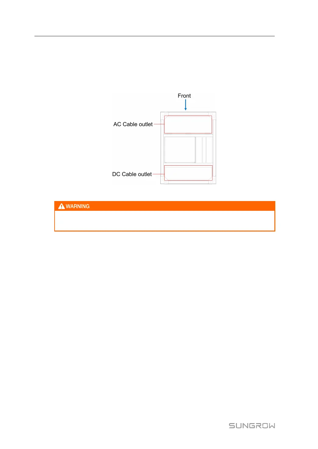
figure 5-1 Position of the positioning opening on the PCS bottom
The bottom cover plate at the cable entry cannot be discarded during cable wiring
and must be reinstalled to ensure protection for internal equipment.
5.2.2 Clearance Space
Precautions for installation spacing
• A distance followed by a specified temperature behind indicates the minimum clearance
under the temperature.
• A distance without a specified temperature indicates the clearance has nothing to do with
the ambient temperature, but is related to the door size and the basic layout distance.
• The layout distance described in this manual only applies to PCSs with the same orienta-
tion. If it is required to open doors of PCSs that are installed face to face at the same
time, please double the distance.
• The followings are ideal layout design. The clearance on site should be greater than the
recommended distance for later operation and maintenance.
• If a sunshade is installed on the top of the machine, the distance from the top of the PCS
to the sunshade must be greater than 1000mm.
Single PCS
In case of a single PCS, the clearances should meet the following requirements:
5 Mechanical Mounting User Manual
 Loading...