60
If different cabinets are not connected by bolts, adopt either of the following two methods to
ensure that they are equipotential.
• Fix the single-core yellow-green cable of at least 25mm
2
to the frame of the PCS enclo-
sure with cable connection plate and bolt. Or
• Connect each device to the equipotential copper bar inside the electrical control room.
6.8.3 Ground of the Shielded Layer of Communication Cable
A standard PCS adopts RS485 communication methods and shielded twisted-pair cables.
Ground the shielded layer to reduce the communication interference.
If RS485 communication cable is selected, the shielded layer must be connected securely
and single point grounded. The grounded place is usually outside the DC PMD or the PCS.
6.9 Communication Connection
Respect all internal connection marks and instructions.
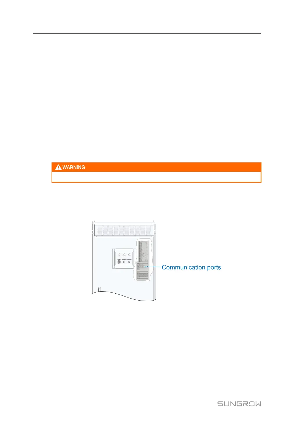
Communication Terminals
There are several communication ports reserved for external connections. The following fig-
ure shows the maintenance communication port:
figure 6-15 Maintenance communication port
Communication Interface
The PCS is designed with standard network port communication interfaces.
The network port communication interfaces are used to establish communication with moni-
toring devices and to upload monitoring data to a monitoring background through communi-
cation cables.
When communication is established between the PCS and the communication devices,
users can view PCS information or set PCS parameters, such as running parameter and
protection parameter, through the Web.
6 Electrical Connection User Manual
 Loading...