59
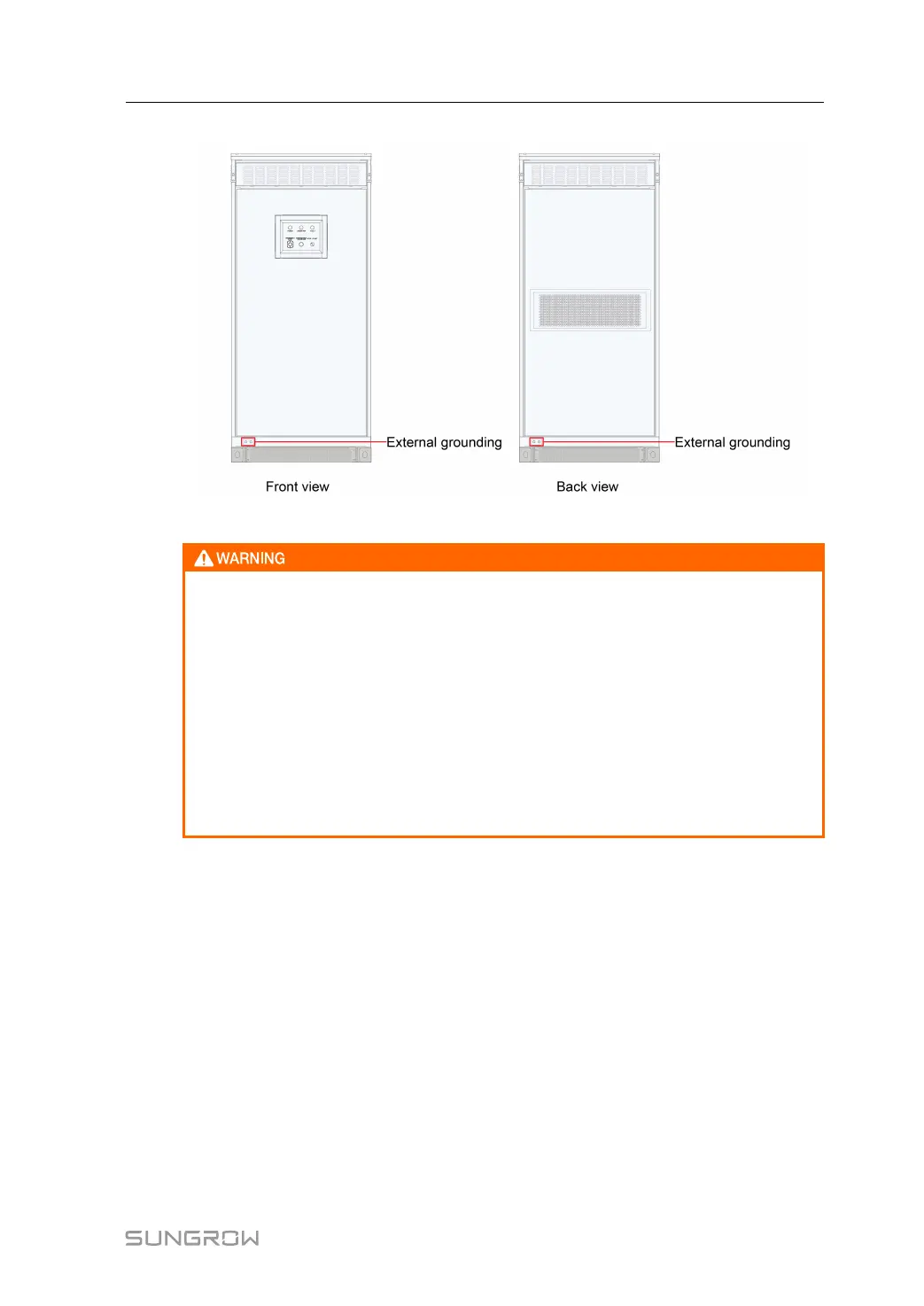
figure 6-14 Positions of the external grounding points
The on-site PE cable shall be connected to the external grounding terminal of the
PCS cabinet. It is strictly prohibited to connect it to the grounding bar inside the
PCS cabinet!
The external grounding terminal of the PCS cabinet is covered with a protective
sticker, which must be torn off before on-site ground connection. Otherwise, the
ground connection is inadequate and will affect system performance.
Devices inside the PCS cabinet have been connected to the internal floating equi-
potential grounding copper bar. The installation hole in the floating grounding cop-
per bar is reserved for the power cable connection, and no on-site PE cable can be
connected to it.
6.8.1 Connection of Ground Copper Bar
It is crucial to ground all PCSs via PEN conductor.
The PCS enclosure and internal components (for example, SPD) that needed to be
grounded have been firmly connected to the PE copper bars on the bottom of the PCS cabi-
net. Connect the external grounding point to the PE copper bar in the installation field using
the grounding cable with a cross-sectional area of at least 50 mm
2
. The grounding resist-
ance must not exceed 4Ω.
6.8.2 Equipotential Connection of Multiple Devices
There are initial charge cabinet and other electrical devices inside the electrical control room.
During ground connection, perform equipotential bonding of all electrical devices to avoid
current appearing in the shielded layer of the communication cable (caused by potential dif-
ference of devices).
User Manual 6 Electrical Connection
 Loading...