8
SSyymmbblloo EExxppllaannaattiioonn
Danger to life due to high voltages!
Do not touch live parts for 10 minutes after disconnection
from the power sources.
Only qualified personnel can open and maintain the inverter.
Additional grounding point.
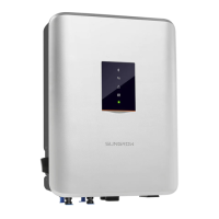
2.4 LED Indicator
The LED indicator on the front of the inverter can indicate the present working state of
the inverter.
Table 2-1 State description of the LED indicator
LLEEDD ccoolloorr SSttaattee DDeeffiinniittiioonn
Blue
On
The inverter is normally running.
Flashing
The DC or AC side is powered on and the
device is in standby or startup state (not
feeding power into the gird).
Red
On
A system fault has occured.
Gray
Off
Both the AC and DC sides are powered down.
2.5 Circuit Diagram
The following figure shows the main circuit of the inverter.
2 Product Description User Manual