23
5.4.1 Additional Grounding Requirements
All non-current carrying metal parts and device enclosures in the PV power system
should be grounded, for example, brackets of PV modules and inverter enclosure.
When there is only one inverter in the PV system, connect the additional grounding
cable to a nearby grounding point.
When there are multiple inverters in the PV system, connect grounding points of all
inverters and the PV array frames to the equipotential cable (according to the onsite
conditions) to implement an equipotential connection.
Ensure that the grounding resistance should be less than 10 Ohm.
5.4.2 Connection Procedure
Additional grounding cable and OT/DT terminal are prepared by customers.
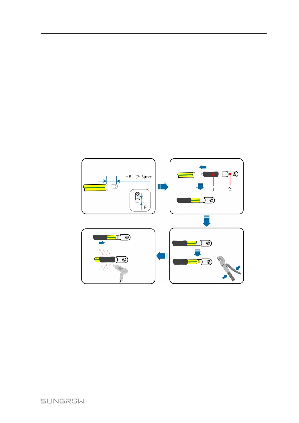
Step 1 Prepare the cable and OT/DT terminal.
1: Heat shrink tubing
2:OT/DT terminal
Step 2 Remove the screw on the grounding terminal and fasten the cable with a screwdriver.
User Manual 5 Electrical Connection