21
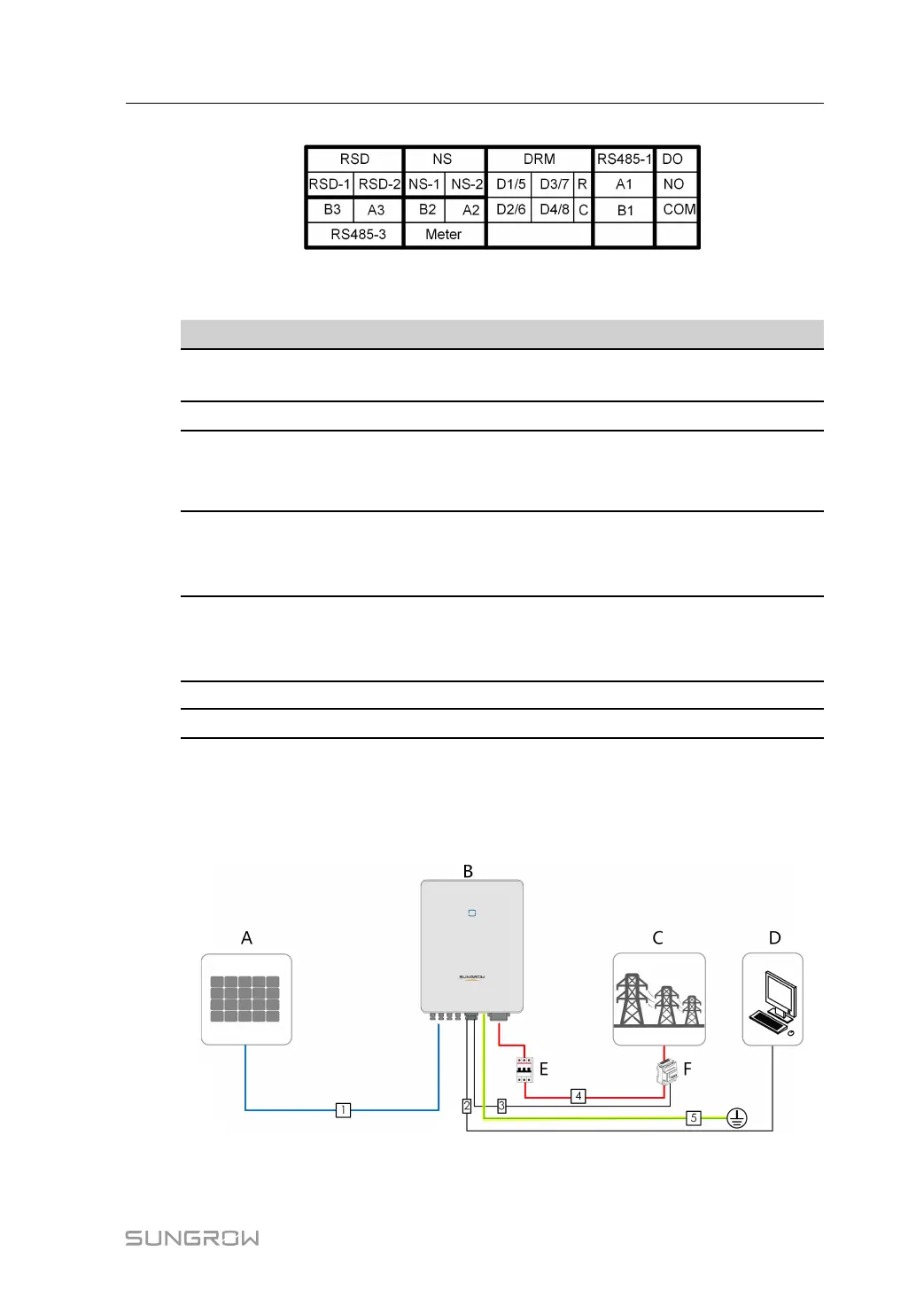
FFiigguurree 55--22 Label of COM2 Terminal
Table 5-2 Label Description of COM2 Terminal
LLaabbeell
DDeessccrriippttiioonn
RSD
RSD-1,
RSD-2
Reserved
NS
NS-1, NS-2
For NS protection ("DE")
DRM
D1/5, D2/6,
D3/7, D4/8,
R, C
For external Demand Response Enabling Device ("AU"/
"NZ")
RS485-1
A1, B1
For inverter daisy chain
(Cannot be used simultaneously with COM1 port for
WiNet-S)
DO
NO, COM
For external alarm, e.g. light indicator and/or buzzer
The external DC voltage should not be higher than 30 V
and the current not higher than 1 A.
RS485-3
A3, B3
Reserved
Meter
A2, B2
For the smart energy meter
5.3 Electrical Connection Overview
The electrical connection should be realized as follows:
(A) PV string (B) Inverter (C) Grid
(D) External device (E) AC circuit breaker (F) Smart energy meter
User Manual 5 Electrical Connection