10
• Protection Function
Several protective functions are integrated in the inverter, including short circuit
protection, grounding insulation resistance surveillance, residual current protection,
anti-islanding protection, DC overvoltage/overcurrent protection, etc.
FFaauulltt AAllaarrmm
The inverter has integrated a DO relay for the local fault alarm. The additional equipment
required is a light indicator and/or a buzzer that needs to be powered by the grid.
After the connection, if a fault occurs, the DO dry-contact will switch on automatically to
signal the external alarm.
DDRRMM ((""AAUU""//""NNZZ""))
The inverter provides terminals for connecting to a demand response enabling device (-
DRED). After the connection, the DRED asserts demand response modes (DRMs). The
inverter detects and initiates a response to all supported demand response modes listed
in the following table.
Table 2-2 Demand Response Mode Explanation
MMooddee EExxppllaannaattiioonn
DRM0 The inverter is in the state of standby.
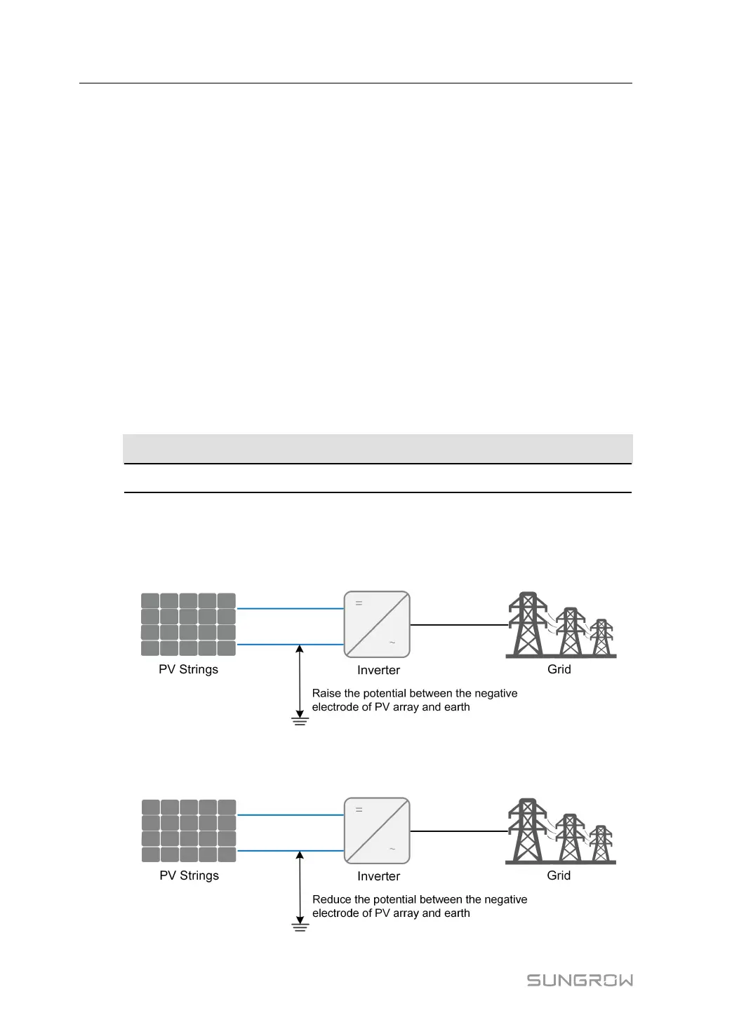
PPIIDD RReeccoovveerryy
• For positive voltage scheme, after the PID function is enabled, the voltage to ground
of all PV strings is greater than 0, that is, the PV string-to-ground voltage is a positive
value.
• For negative voltage scheme, after the PID function is enabled, the voltage to ground
of all PV strings is lower than 0, that is, the PV string-to-ground voltage is a negative
value.
2 Product Description User Manual