12 Appendix III: AS/NZS 4777.2 Compliant User Manual
96
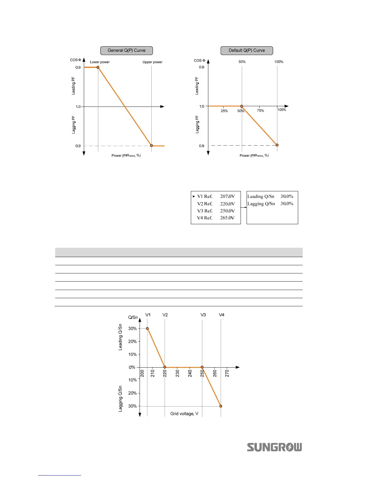
Fig. 12-1 Reactive Power Regulation Curve in Q(p) Mode
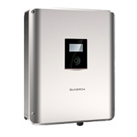
12.2.3 “Q(u)” Mode
The reactive power output of the
inverter varies in response to the grid
voltage.
Tab. 12-3 “Q(U)” Mode Parameter Explanations
Parameter Explanation Default Range
V1 Ref. Grid voltage reference value 1 207.0 V Not applicable
V2 Ref. Grid voltage reference value 2 220.0 V 216 V–230 V
V3 Ref. Grid voltage reference value 3 250.0 V 235 V–255 V
V4 Ref. Grid voltage reference value 4 265.0 V 244 V–265 V
Leading Q/Sn Q/Sn value of voltage V1 Ref. 30 % 0–60 %
Lagging Q/Sn Q/Sn value of voltage V4 Ref. 30 % 0–60 %
Fig. 12-2 Reactive Power Regulation Curve in Q(u) Mode