2 System Solution User Manual
6
No. Name Description
7 Communication connection RS485, Ethernet, CAN, AI, DO and DRM.
8 Hasp lock To open/lock the enclosure lid.
9 Second PE terminal For reliable grounding.
10 LCD display panel Human-computer interaction interface.
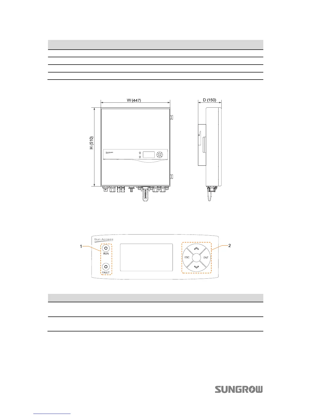
The following figure shows the dimensions of the inverter.
Fig. 2-2 Outline Dimensions (unit: mm)
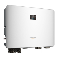
The LCD display panel with two indicators and four buttons is on the front of the
inverter.
Fig. 2-3 LCD Display Panel
No. Name Description
1 LED indicators
“RUN” and “FAULT”, from which user can know the current
state. For detailed definition, see Tab. 7-5.
2 Buttons
User can operate the LCD menu via the four buttons.
For detailed functions, see Tab. 7-1.