User Manual 6 Electrical Connection
31
Label Description
AC-Grid AC terminal to the utility grid.
Backup Ctrl
Two holes for the control cable and DI cable of the backup
box STB5K.
PV1+, PV1-, PV2+, PV2- Terminals for the DC cables.
ON, OFF DC switch.
Com.
Cable glands for Ethernet, RS485, PT1000, CAN, DO and
DRM.
Wi-Fi Terminal for the Wi-Fi module.
BAT+,BAT-
Cable glands for the battery power cables.
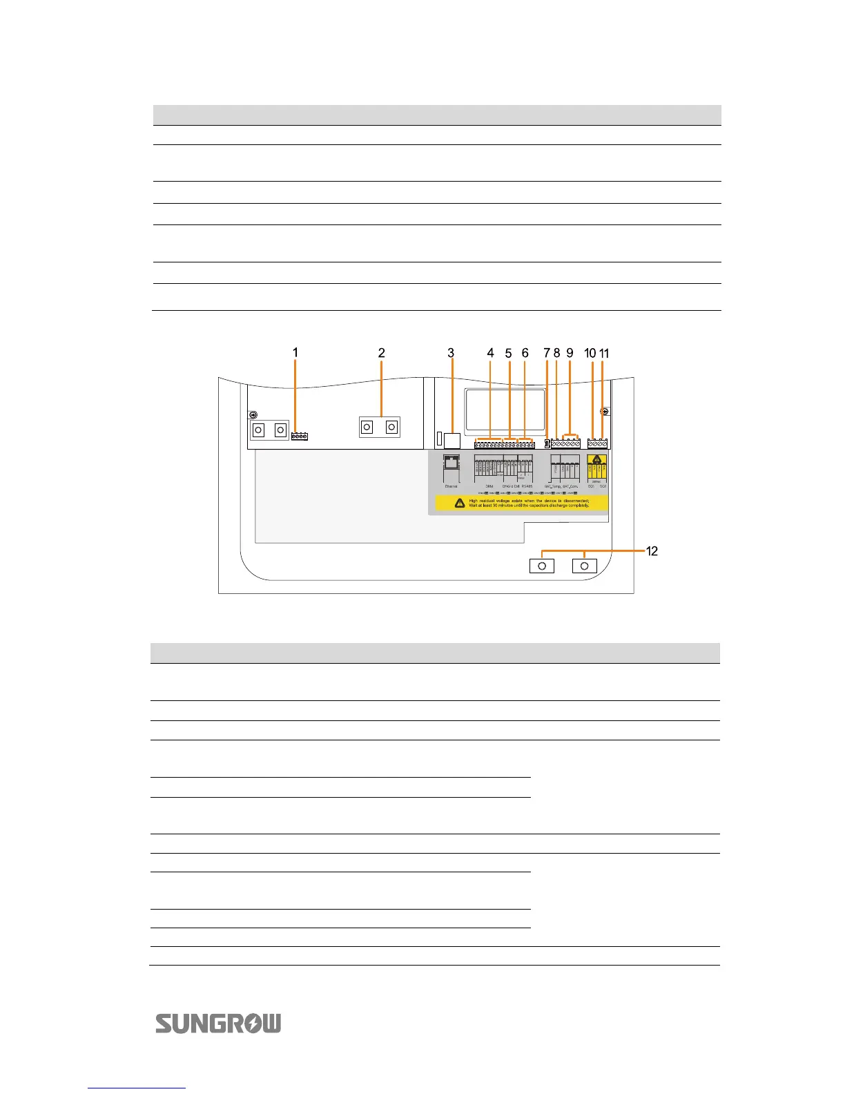
Connection terminals on the inner configuration circuit board are shown below:
Fig. 6-2 Configuration Circuit Board Inside the Inverter
No.
Label Connection Tool Requirements
1 C1, C2 Backup box STB5K
Flat-head screwdriver
with an open end of 3 mm
2 Copper PV (Parallel mode) Phillips screwdriver
3 Ethernet Communication -
4 DRM
Demand response enabling
device (DRED)
Flat-head screwdriver
with an open end of 2 mm
5 DI Backup box STB5K
6 RS485
A1, B1 for the battery,
A2, B2 for the meter
7 120 ohM RS485 -
8 BAT_Temp. Temperature sensor PT1000
Flat-head screwdriver
with an open end of 3 mm
9
BAT_Com.
(CANH, CANL)
Battery communication
10 DO1 Power management
11 DO2 Earth fault alarm
12 BAT+, BAT- Battery Phillips screwdriver