A-3
Appendix A: Flash Tools
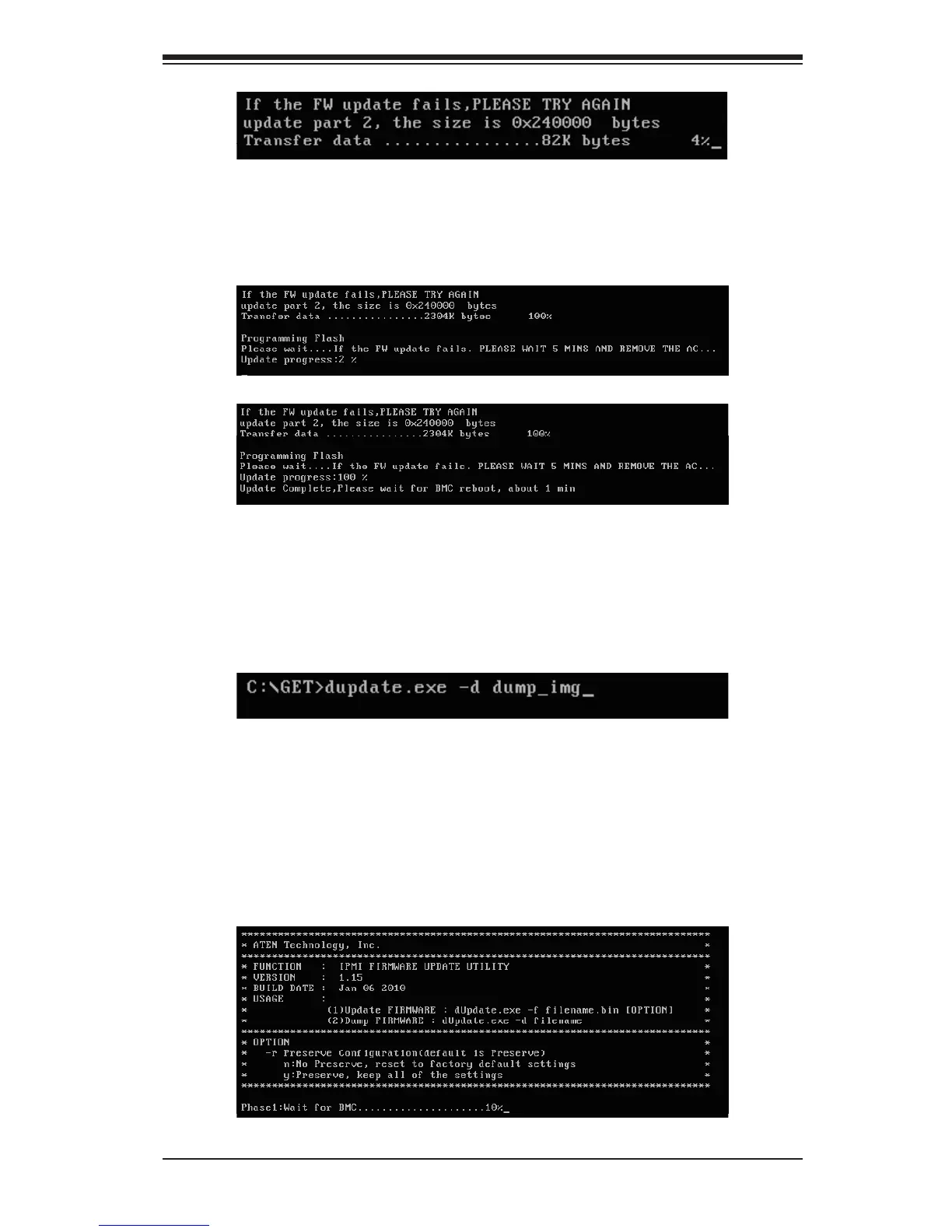
2. Phase 2 is to ash the new rmware. The progress of rmware updating will
be displayed as shown in Figure 6. The BMC will reboot after the rmware
is completely updated. Please wait for the BMC to complete system reboot
(Figure 7).
Figure 5: Transferring (Part 2)
Figure 6: Progress of Firmware Updating
Figure 7: Updates Completed
Dumping Firmware from the BMC via KCS channels
The user can dump the rmware by typing <dupdate.exe –d [lename].> Flash
Tools will dump the rmware into the le that the user has assigned in the previous
command. In the example given in Figure 8, Flash Tools will dump the rmware
to dump_img.
Figure 8: Example of Firmware Dumping via KCS
There are two phases in rmware dumping.
1. During Phase 1, the Flash Tools Utility is waiting for the BMC to prepare the
rmware for dumping. As soon as preparation is complete, the Flash Tools Util-
ity will enter Phase 2.
2. In Phase 2, the Flash Tools utility gets the rmware from the BMC. The user
can see the progress on the screen as shown in Figure 10.
Figure 9: Phase 1- Flash Tools Waiting for the BMC to Prepare Data
 Loading...