3
TimeSource 3100 53
Installation
097-72020-01 Issue 9: November 2003
2
5
3
SSSSSSSSSSS SSSS S SSSSS SSSS SSS S SSS S SSSSS S
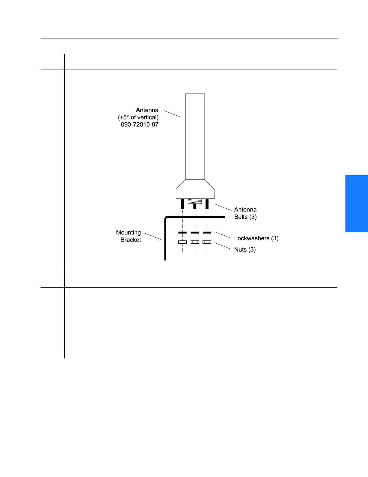
2 Slide the antenna bolts through the holes in the mounting bracket, then attach the antenna
to the bracket, using the provided three nuts and three lockwashers.
3 Using a plumb line or bubble level, ensure the antenna is within 5° of vertical
(perpendicular to the horizon), and tighten the mounting bracket bolts.
4 Bolt the lightning suppressor mounting plate to a flange that is attached to a valid earth
ground. The roof ring ground system, a Central Office grounding plate, and building
structural steel are examples of valid earth ground points. If the mounting plate cannot be
bolted to a valid earth ground, bolt the mounting plate to a point within 4.6 m of the chosen
valid earth ground. If the mounting plate is to be installed in a nonmetallic junction box,
perform the installation, and bolt the assembly near the chosen valid earth ground.
Note: A junction box must have inside dimensions of 7 cm by 7 cm by 4 cm to hold the
mounting plate and attached components.
Procedure B. Antenna Mounting and Cable Connection (cont’d)
Step Procedure
 Loading...