62 TimeSource 3100
Installation
097-72020-01 Issue 9: November 2003
SSSSSSSSSSS SSSS S SSSSS SSSS SSS S SSS S SSSSS S
3
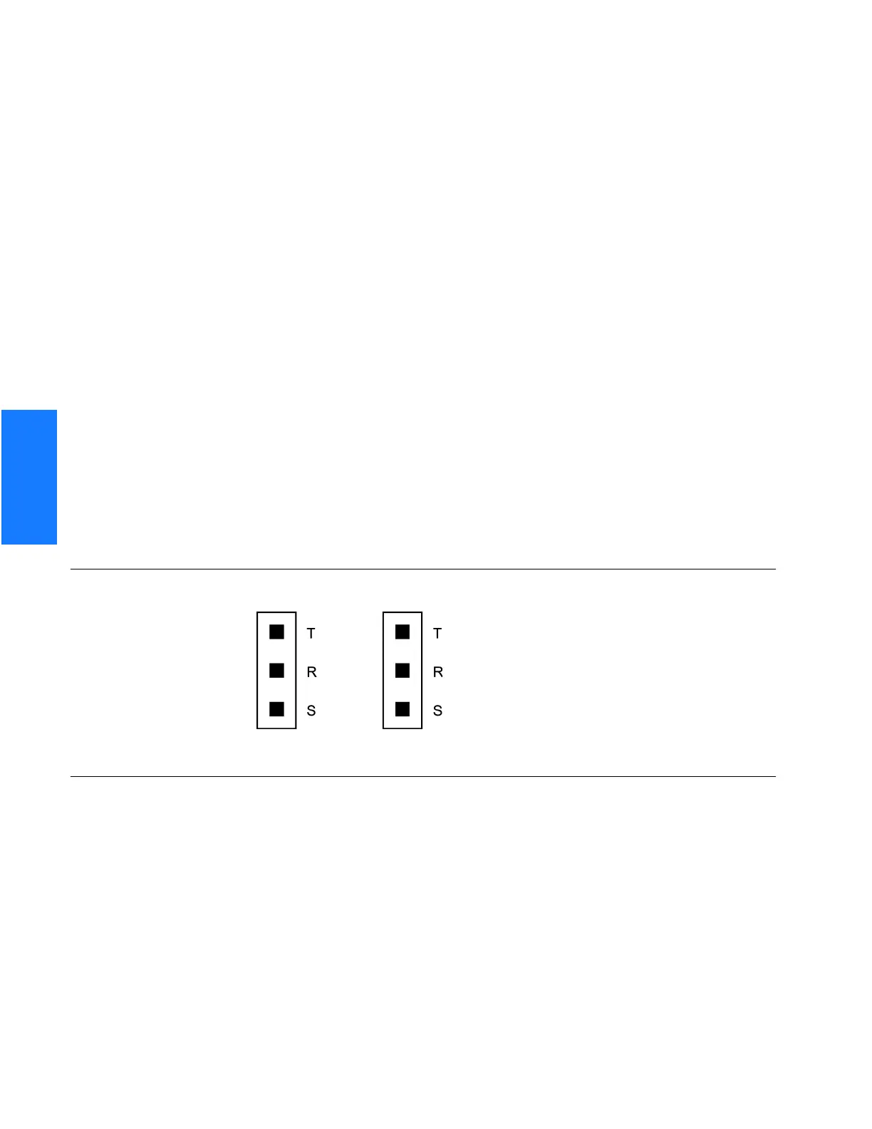
E1 or Analog Synchronization Outputs
Connect the E1 or analog synchronization outputs at the wire-wrap pins or BNC connectors
labeled El OUT A and El OUT B. If using the wire-wrap pins, connect the tip wire to the
pins labeled T, the ring wire to the pins labeled R, and the shield to the pins labeled S. See
Figure 13 for the location of the connectors and pins, and Figure 15 for the wire-wrap
connections.
Notes:
1. For wire-wrap connections, the shield pin is provided to ground the cable shield at the
shelf, if required. Normally, the shield is grounded at the source. Grounding the shield at
both ends is not recommended.
2. A BNC connector can be used for one output, and a wire-wrap connector can be used for
the other output, but do not use the BNC and wire-wrap connectors of the same output
simultaneously. For example, a BNC connector can be used for output A and the wire-
wrap pins for output B, but do not use the output A BNC connector with the output A
wire-wrap connector.
Warning: Because the El output circuits do not provide lightning protection, do not
connect the El output line directly to a point outside the building. Failure to observe
this warning may result in equipment damage.
Figure 15. E1 or Analog Output Wire-Wrap Connections
 Loading...