60 TimeSource 3100
Installation
097-72020-01 Issue 9: November 2003
SSSSSSSSSSS SSSS S SSSSS SSSS SSS S SSS S SSSSS S
3
Frame Ground
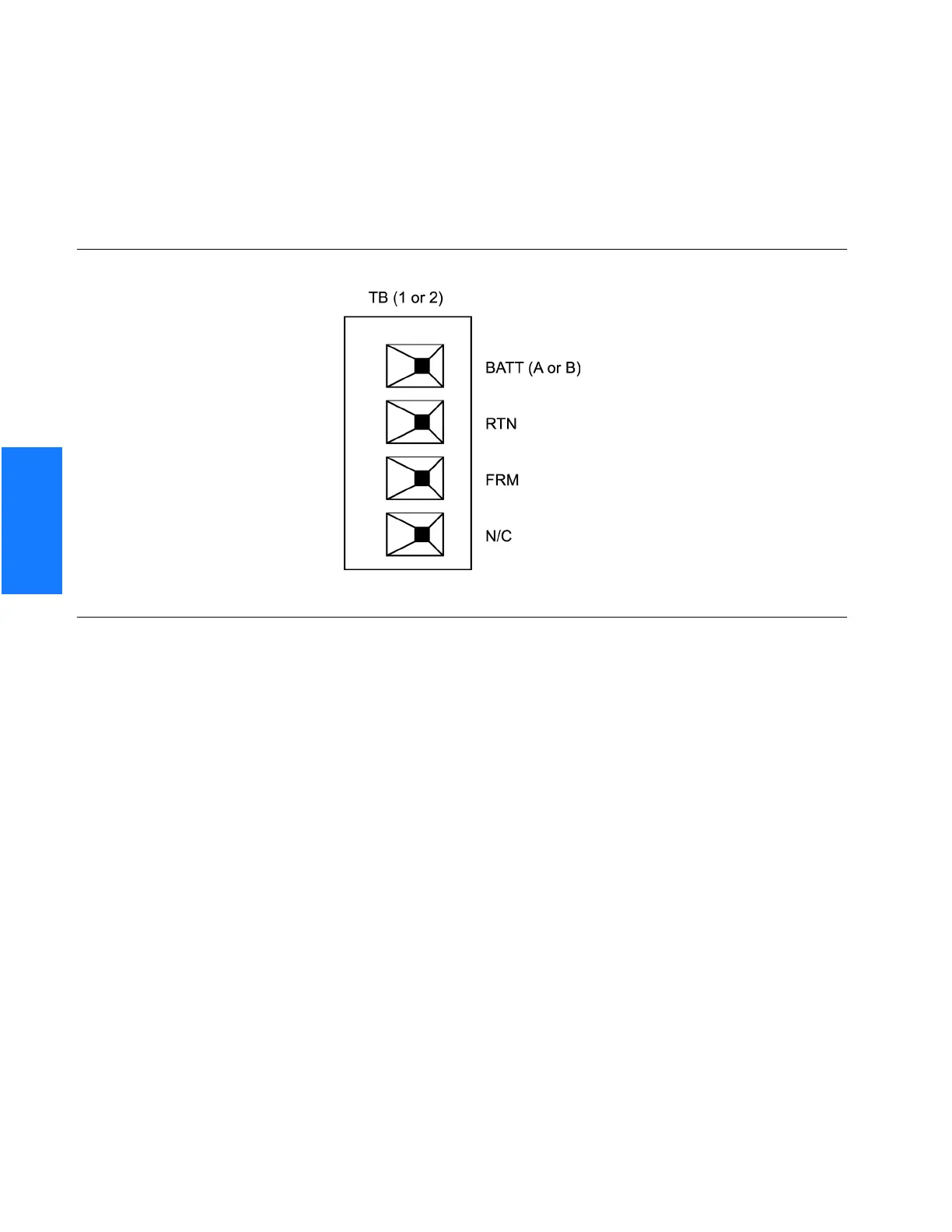
Frame ground enters through the four-position power terminal blocks labeled TB1 and TB2.
Figure 13 shows the location of the terminal blocks, and Figure 14 shows the terminal block
connections.
Figure 14. Connector Panel Terminal Block Connections
Ensure the frame ground wires are long enough to reach from the shelf connector panel to
the frame ground connection. Use one 1.47 mm (16 AWG) green insulated wire to connect
the FRM terminal of power terminal block TB1 to the frame ground, and use another 1.47
mm (16 AWG) green insulated wire to connect the FRM terminal of TB2 to frame ground.
Make the ground connection, following one of the methods described below, depending on
whether a ground rod is installed:
With ground rod:
Solder the connection to the 4.115 mm (6 AWG) frame ground rod that is run vertically on
each side of the rack, if provided. Two methods are acceptable:
• Crimp an appropriate-size spade lug to the 1.47 mm (16 AWG) wire, bend the lug
around the frame ground rod, and solder.
• Strip enough insulation from the 1.47 mm (16 AWG) wire to permit three complete
turns around the frame ground rod, and solder.
Note: When soldering, use a 25 watt soldering iron to ensure the frame ground rod is heated
sufficiently to prevent a cold solder connection
.
 Loading...