Home
Tailift
Drill
TPR720A
Page 34 (Instruction to Switches)
Tailift TPR720A - Instruction to Switches
86 pages
Manual
Save Page as PDF
To Next Page
To Next Page
To Previous Page
To Previous Page
Loading...
5-8
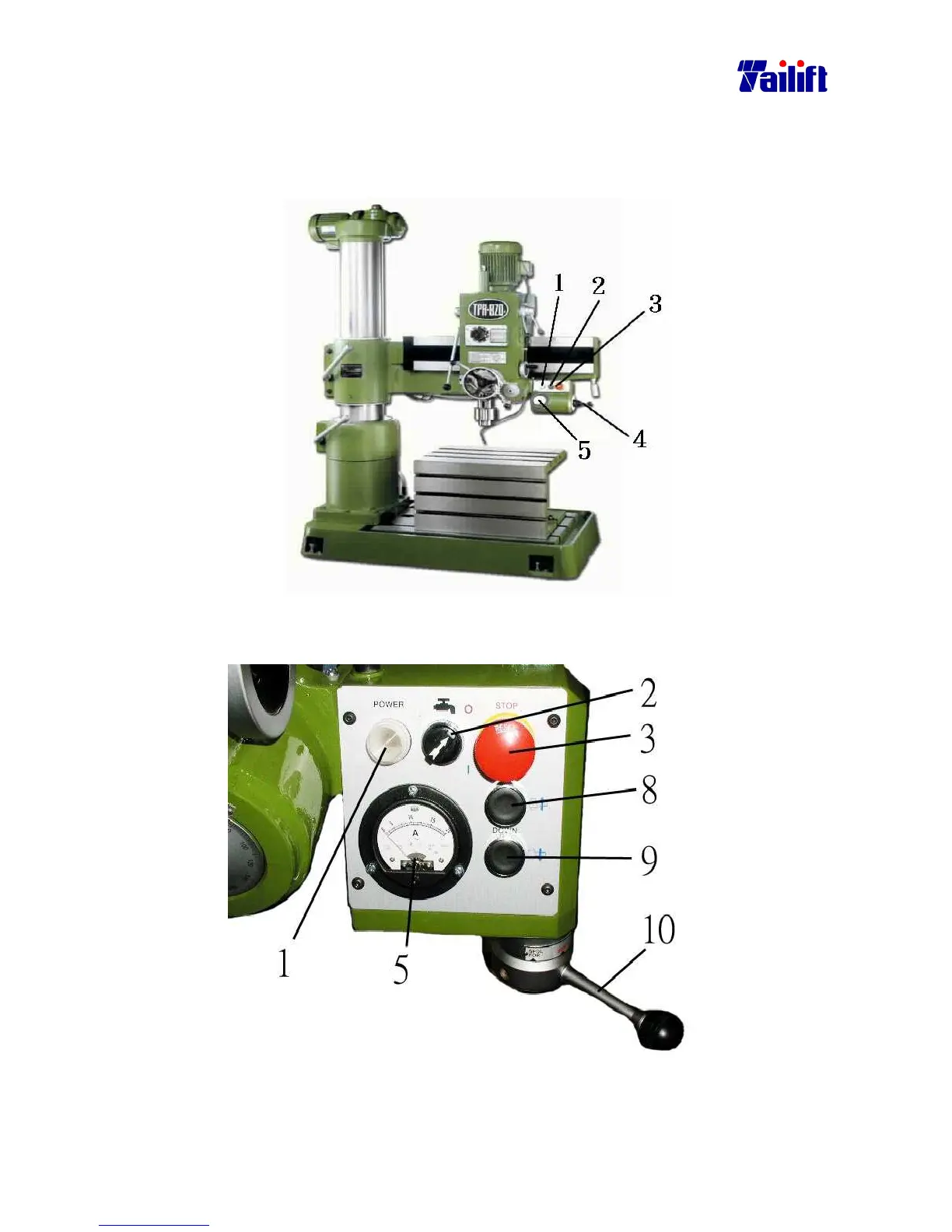
5.2 Instruction to sw
itches.
Ⅰ
Ⅰ
Ⅰ
Ⅰ
.( For TPR-720A
, TPR-820A, TPR-920A)
(Type I)
The front view of T
PR-820A
Description fo
r Switc
hes.
( For TP
R-720A, TPR-820A, TP
R-920A)(Type II)
The rear view
of TPR-820A
33
35
Table of Contents
Main Page
CHAPTER 1 Safety Guidelines
2
Please Follow the below Basic Safety Principles
2
Precautions for the Transportation and Installation
2
Precautions for Operation
3
Precautions for Checking and Maintenance
3
Warning Labels and Mark on the Machine
4
Warning Labels and Mark Introduction
4
CHAPTER 2 General Specifications
8
The Anticipated Machine Life
8
Machine Dimensions
8
The Machine
9
Parts
9
I for TPR-720A, TPR-820A, TPR-920A
9
Only for TPR-1100
10
Tpr-720A
11
Specifications
11
TPR-820A Specification
12
TPR-920A Specification
13
TPR-1100 Specification
14
Standard and Option Accessories
15
Operation Position and Noise Level
15
Operation Position
15
The Noise Level
15
CHAPTER 3 Preparation to Install
16
Space and Room Requirement
16
Floor Requirement
16
Space Requirement
17
Environment Requirement
18
Power Supply Requirement
18
Electric System Calculation
19
CHAPTER 4 Transportation and Installation
21
Disassembly and Packaging
21
General
21
Packaging
21
Transportation
22
The Diagram of the Machine Weight and Its Gravity Center
22
The Movement of the Machine
22
The Order to Pack
23
Installation of the Machine
24
Have the Machine Set Onto the Fastening Bolts of the Crate Base
24
Level Adjusting
25
The Installation of the Electricity
25
The Test after Installation
26
The Procedure for Dismantling the Machine
26
CHAPTER 5 Operation
27
A Brief Introduction to the Relevant Operation Hardware
27
For TPR-720A, TPR-820A, TPR-920A)
27
For TPR-1100)
30
Safty Protective Device
33
Instruction to Switches
34
For TPR-1100)
36
Installation of the Clamp(Work Piece
38
General
38
Introduction of the Vise and the Clamping of the Work Piece
38
Universal Clamp and the Clamping of the Work Piece
39
Installation and Change of the Drilling Bit
41
The Assembly and Disassembly of the Drilling Head and Clamp
42
The Assembly and Disassembly of the Straight Handle Drill Bit
44
Power on and off
45
Power on
45
Power off
45
Work Light
45
Cutting Fluids
45
Elevating the Arm
46
Rotate the Arm Right or Leftwards
47
Rotate the Arm to or Backwards
48
Change the Spindle Speed
49
For TPR-720A, TPR-820A, TPR-920A
49
I Speedometer
49
Change Spindle Speed
50
For TPR-1100
51
Change Spindle Speed
52
Automatic Feed
54
Automatic Feed Rate Table
54
Change the Feed Rate as the Following Way
54
Suppose that the Work Piece Is by the Machine
54
How to Preset the Depth of the Power-Feed
55
The Spindle
57
Threading
57
The Assembly and Disassembly of the Work Table
58
Cutting Fluids for All Kinds of Material
58
CHAPTER 6 Adjustment
59
General
59
The Arm Clamping Lever
59
The Gap Adjustment between the Gearbox and the Arm Rail
60
For TPR-720A, TPR-820A, TPR920A)
60
For TPR-1100)
61
Adjust the Engagement between the Feed Trip Lever and the Clutch
62
CHAPTER 7 Maintenance
63
General
63
Daily Maintenance
63
Clearing
63
Please Clean Every Parts Using a Metal Brush and a Rag, Dipped with Oil, to Rub Them
63
The Way to Clean Iron Filings
64
Lubrication
65
Change Oil Inside of the Speed Reduction of the Arm Elevating Motor
66
Chang the Oil Inside the Gearbox
67
Replace the Cutting Fluids
68
Maintenance and Replacement Period
69
Waste Disposition
69
CHAPTER 8 Troubleshooting
70
The Spindle Overloads and the Relay Jumps
70
The Cause
70
The Solution
70
The Spindle Overloads and the Fuse Burns out
70
What if the Drill Bit Get Broken
71
What if the Screw Tap Get Broken
71
How if a Person Is Entangled
71
Table of Contents
72
CHAPTER 9 Annex
81
Electrical Circuit Diagram(TPR1100 CE Standard)
81
Electrical Circuit Diagram(TPR720A,TPR820A,TPR920A Standard)
84
Related product manuals
Tailift TPR1230
99 pages