TM9100 Service Manual Interface Fault Finding 163
© Tait Electronics Limited August 2005
8 Interface Fault Finding
Introduction This section covers the diagnosis of faults involving signals output from or
input to the radio’s internal circuitry via the control-head, internal options,
power, or auxiliary connectors. For most inputs and outputs, filtering or
basic processing is applied between the internal circuitry and the connectors.
Internal and
Connector Signals
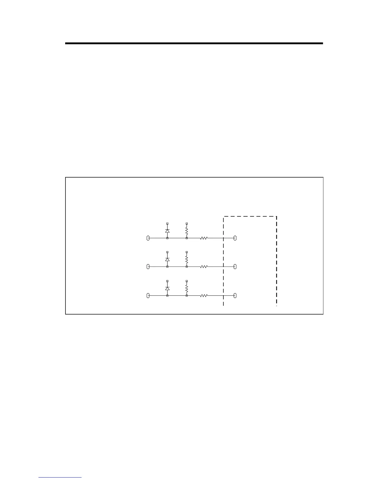
The signals at the internal circuitry and those at the connectors are
distinguished as internal signals and connector signals respectively. On the
circuit diagram for the internal circuitry, dashed lines enclose connector
signals. Internal signals are all named signals outside these enclosures. In
Figure 8.1, which shows part of the internal options connector as an
example,
IOP GPIO7 is a connector signal and ITF IOP GPIO7 is an internal signal.
Types of Signals The connector and internal signals can be of three types:
■ output lines
■ input lines
■ bi-directional lines
For diagnosing faults in these three cases, carry out Task 1, Task 2 or Task 3
respectively. Where components need to be replaced to rectify faults, refer
to Figure 8.3 to Figure 8.4 for the locations of the components. These
figures show the three areas of the main board where the components of the
interface circuitry are situated.
Figure 8.1 Example illustrating the convention for internal and connector signals
+3V3_CL +3V3
D705
BAV70W
2
3 R723
33K
R731
1K0
IOP_GPIO7
1B2
6B4
ITF_IOP_GPO7
+3V3_CL +3V3
D706
BAV70W
1
3 R724
33K
R732
1K0
IOP_GPIO6
1B2
ITF_IOP_GPO6
+3V3_CL +3V3
D706
BAV70W
2
3 R725
33K
R733
1K0
IOP_GPIO5
1B2
ITF_IOP_GPO5
TO
INTERNAL
OPTIONS
CONNECTOR
 Loading...


