434 TMAA02-08 Keypad Microphone TM9100 Service Manual
© Tait Electronics Limited August 2005
16.3 Radio Programming
The radio does not need to be programmed to recognize the presence of a
keypad microphone, as this is automatically done when the radio is
powered on.
However, there are a few related fields that should be configured, as
required, to enable the keypad microphone to be used effectively. For
example, in conventional mode there are check boxes called “Selcall Call
Dialling”, “DTMF Call Dialling” and “Phone Patch Call Dialling”. There
is also an option “Conventional Dialling Type” field, where you can
program the radio to dial labels or channels from the default display.
Refer to the online help of the programming application for more information
about these programming options.
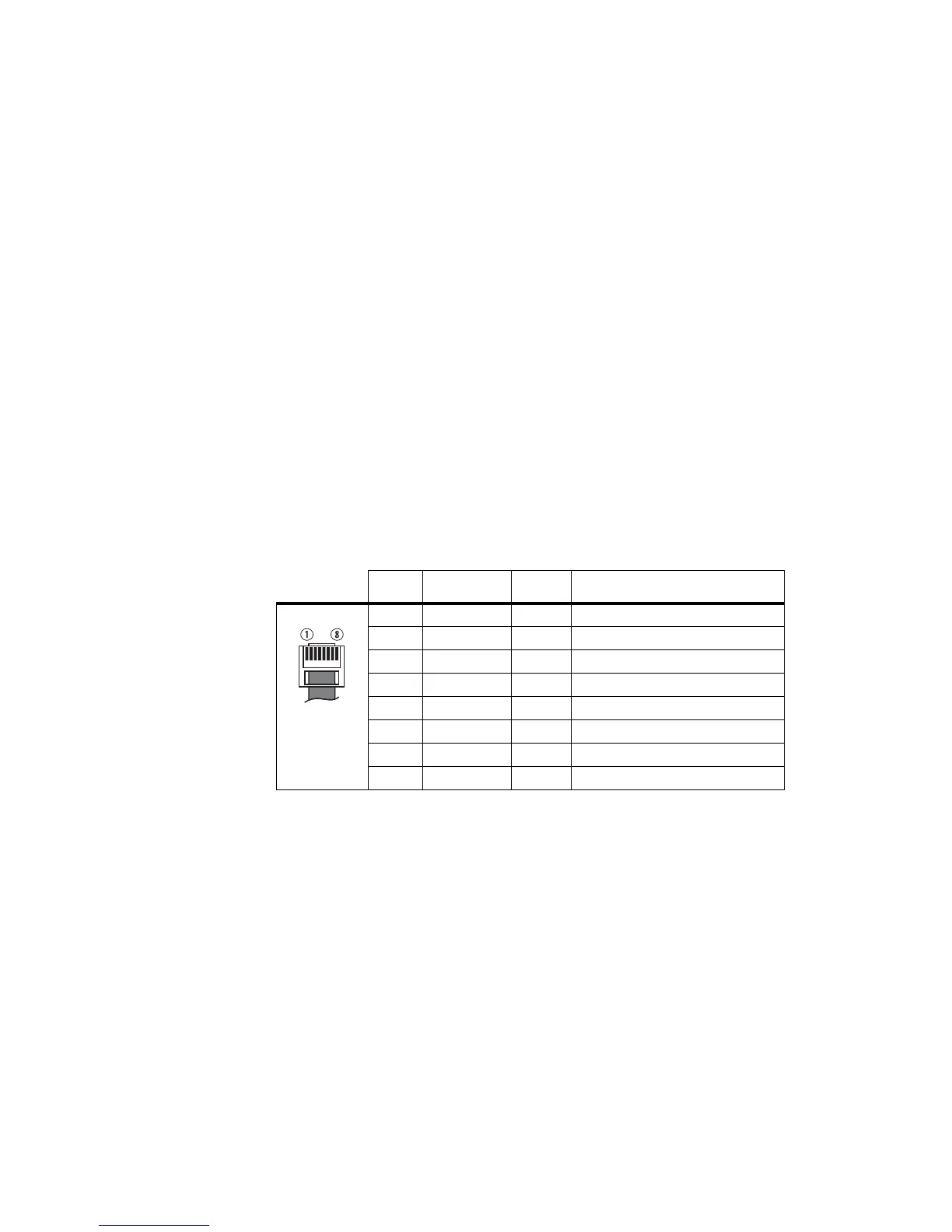
16.4 Interface Specification
The following table and diagram summarizes the signals used for the keypad
microphone on the radio’s microphone connector and shows the interface
between the keypad microphone and the radio.
16.5 Circuit Description
The microphone has a standard 12-key telephone keypad which is
connected to a micro-processor. The micro-processor performs the keypad
scanning using eight GPIO lines. When a valid keypress is detected, a serial
command is sent from the microphone.
Table 16.1 Keypad microphone connector - pins and signals
Pin Signal Colour Description
1 RX audio — not connected
2 13.8V black power supply
3 TXD green transmit serial data
4 PTT white PTT and hookswitch
5 MIC blue audio from the microphone
6GND redground
7 RXD yellow receive serial data
8 IO — not connected

 Loading...


