4-153
4
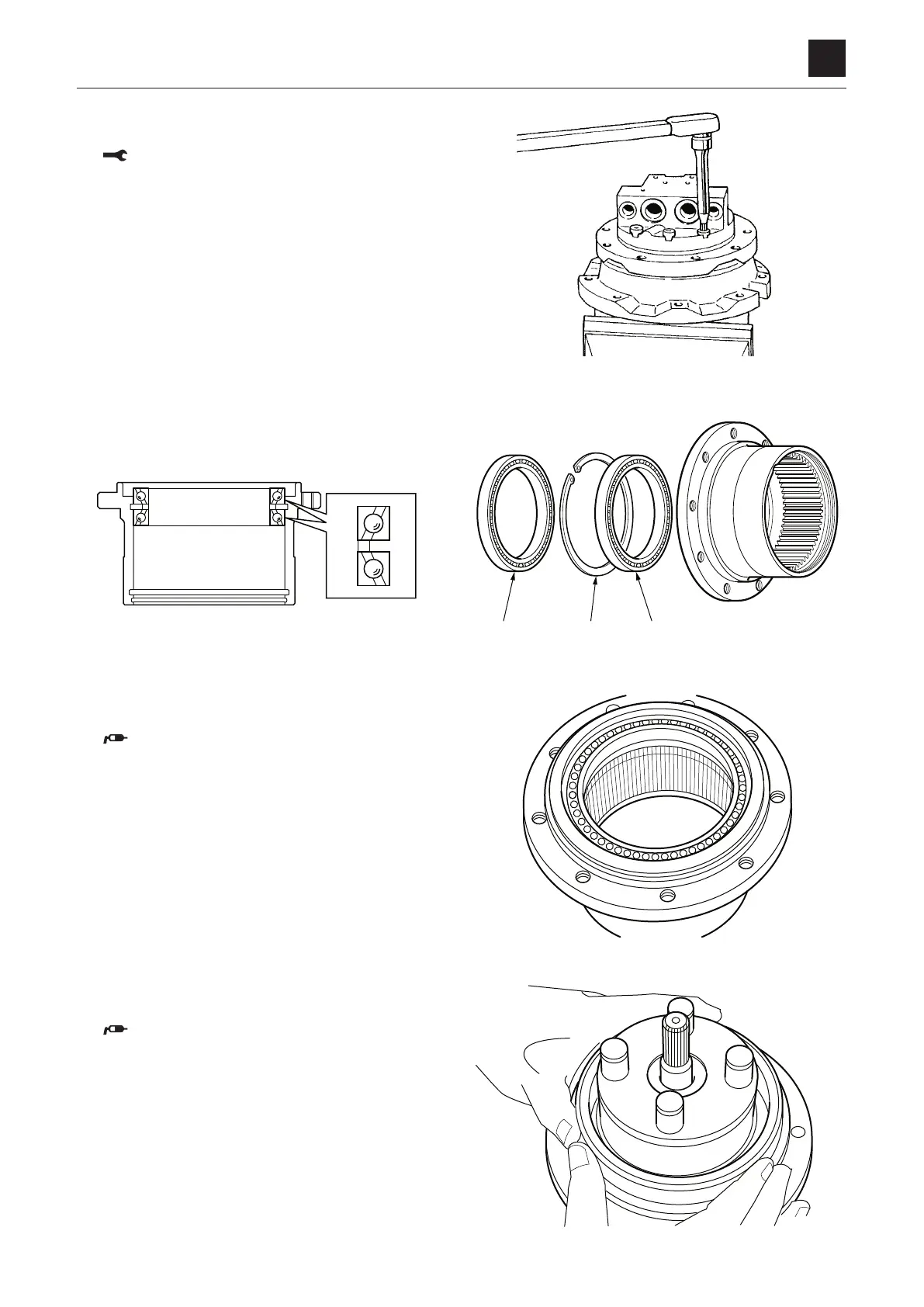
TRAVEL MOTOR
DISASSEMBLY AND ASSEMBLY
25. Secure the hydraulic motor in a vise and tighten the
screws.
Screw: 51 to 64.7 N·m
• Insert an aluminum plate or the like between the
flange holder and the vise to prevent the outer sur-
face of the valve body fr
om being damaged.
Reduction gears
1. Install the bearing (17), snap ring (18) and bearing (17)
on the housing.
• Be careful not to install the bearing a wrong way.
2. Fit the O-ring on the floating seat and install them in the
housing.
Apply grease to the O-ring.
3. Install the floating seat and the O-ring on the flange
holder.
Apply grease to the O-ring.