JOG EXCITE: Service & Maintenance Manual - rev. 1.1
Page 7.14
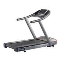
7.13. DISASSEMBLING THE ELECTRONICS BOARDS
Figure 7.13-1
Carry out the procedure described in paragraph
7.12. “Disassembling the electrical box”.
1. Back off the 4 screws a using a medium
Phillips screwdriver.
2. Lift up the cover.
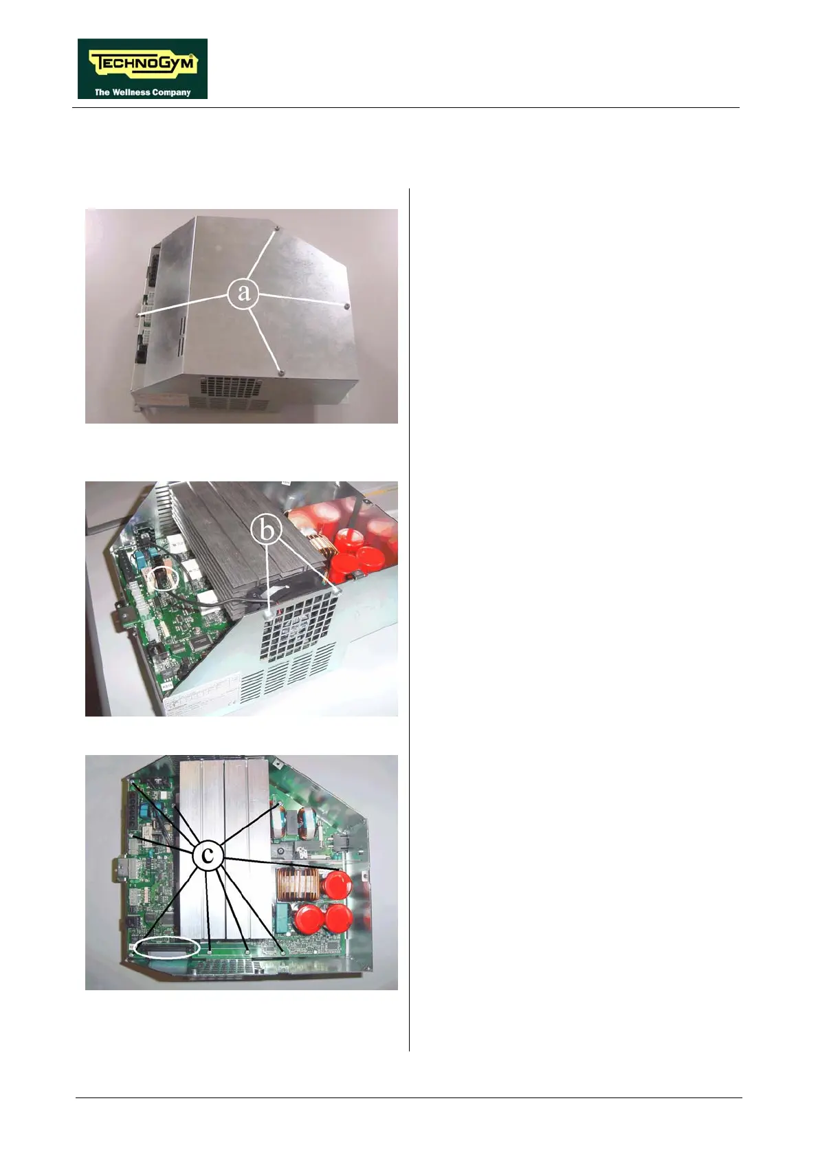
Figure 7.13-2
1. Unplug the fan cable from the AT driver
board.
2. Unscrew the two screws b using a medium
Phillips screwdriver.
3. Remove the fan.
Figure 7.13-3
AT driver board:
1. Unplug the flat cable coming from the AT
power supply board, shown in the picture.
2. Unscrew the screw c using a medium Phillips
screwdriver.
3. Lift up the board paying attention to the
cables connected on the lower side.
Continued on following page →