ENGLISH
UPS EVO DSP PLUS Modular 65 User’s manual
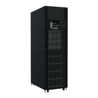
5. Move the Ready Switch to the “ ”( Lock) position, because the Module is Ready to start.
Figure 10.4 – Ready Switch on Power Module
10.1.2 Remove the Power Module
Before removing any Power Module, make sure the remaining Power Modules can
support the critical loads.
At least one Power Module MUST stay in the UPS cabinet except the UPS System is
operating in Maintenance Bypass Mode.
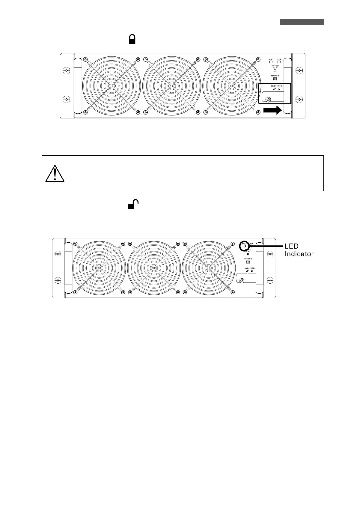
1. Turn the Ready Switch to the “ ” (Unlock) (position.
2. The FAULT Led (red color) is lit to indicate the Power Module Output is OFF and disconnected from UPS
system.
Figure 10.5 – FAULT Led
3. Use a screwdriver to remove the four screws from fixing holes.
4. Two people pull out together and remove the Power Module from its slot.