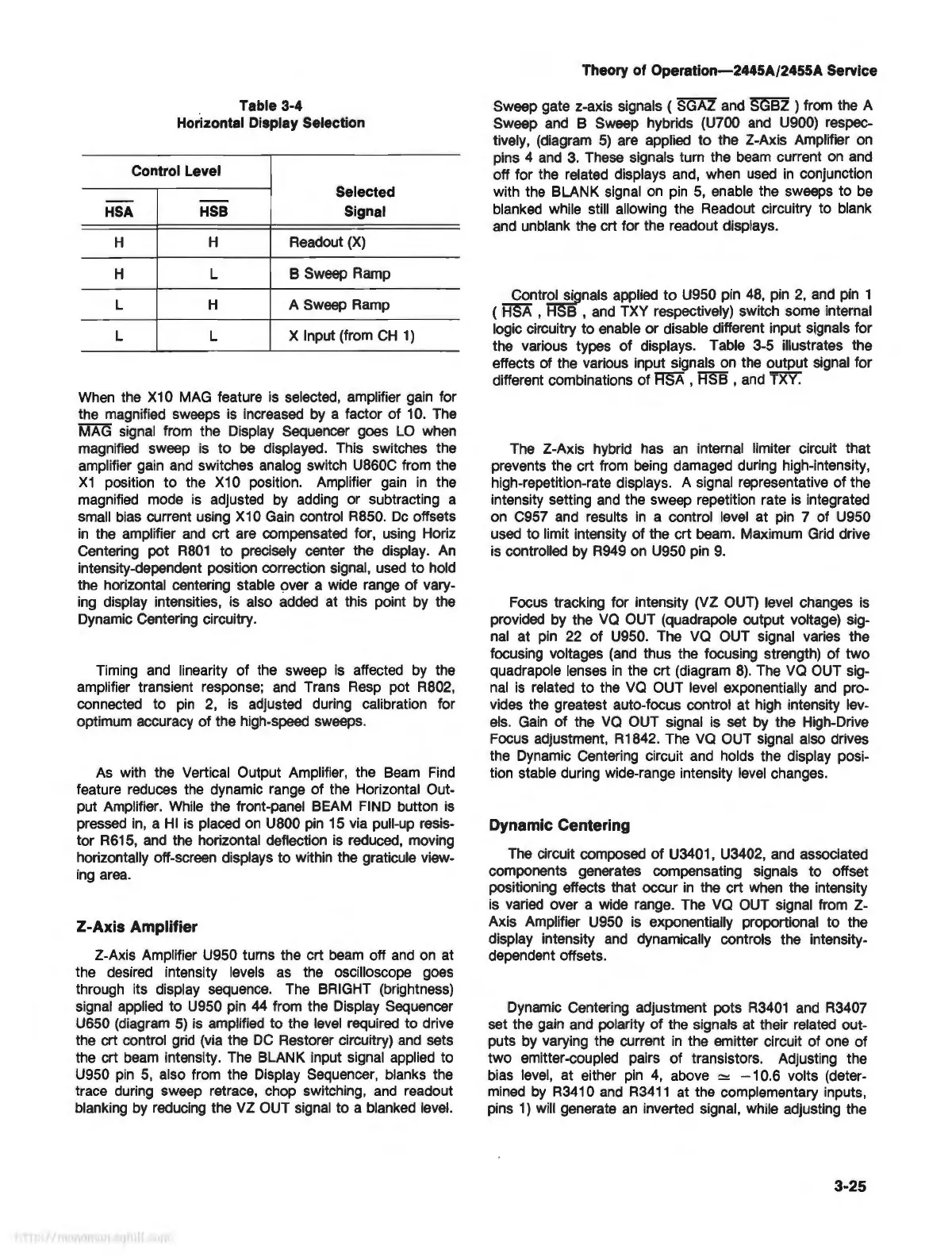
Table 3-4
Horizontal Display Selection
Control Level
Selected
--
--
HSA
HSB
Signal
H
H
Readout
(X)
H
L
B Sweep
Ramp
L H A Sweep
Ramp
L L
X Input (from
CH
1)
When
the
X10
MAG
feature
is
selected, amplifier
gain
for
the magnified sweeps
is
increased
by
a factor of
10.
The
MAG signal from the Display Sequencer goes
LO
when
magnified sweep
is
to
be
displayed. This switches the
amplifier gain
and
switches analog switch U860C from the
X1
position to the
X10
position. Amplifier
gain
in
the
magnified mode
is
adjusted
by
adding or subtracting a
small
bias
current using X
10
Gain
control R850.
De
offsets
in
the amplifier
and
crt are compensated for, using Horiz
Centering pot
R801
to precisely center the display.
An
intensity-dependent position correction signal, used
to
hold
the horizontal centering stable over a wide range of vary-
ing
display intensities,
is
also
added
at this point by the
Dynamic Centering circuitry.
Timing
and
linearity of the sweep
is
affected
by
the
amplifier transient response;
and
Trans
Resp
pot R802,
connected to
pin
2,
is
adjusted during calibration for
optimum accuracy of the high-speed sweeps.
As
with the Vertical Output Amplifier, the
Beam
Find
feature reduces the dynamic range of the Horizontal Out-
put Amplifier.
While
the front-panel BEAM
FIND
button
is
pressed
in,
a
HI
is
placed
on
U800
pin
15
via pull-up resis-
tor R615,
and
the horizontal deflection is reduced, moving
horizontally off-screen displays to within the graticule view-
ing
area
.
Z-Axis
Amplifier
2-Axis Amplifier U950 turns the crt
beam
off
and
on
at
the desired intensity levels
as
the oscilloscope goes
through its display sequence. The BRIGHT (brightness)
signal applied to U950 pin
44
from the Display Sequencer
U650 (diagram
5)
is
amplified to the
level
required to drive
the crt control
grid
(via the
DC
Restorer circuitry)
and
sets
the crt
beam
intensity. The BLANK input signal applied to
U950
pin
5,
also from the Display Sequencer, blanks the
trace during sweep retrace, chop switching,
and
readout
blanking
by
reducing the VZ OUT signal to a blanked
level.
Theory of Operation-2445A/2455A Service
Sweep gate z-axis signals ( SGAZ
and
SGBZ
) from the A
Sweep
and
B Sweep hybrids (U700
and
U900) respec-
tively, (diagram
5)
are applied to the 2-Axis Amplifier
on
pins 4
and
3.
These signals turn the
beam
current
on
and
off for the related displays and, when
used
in
conjunction
with the
BLANK
signal
on
pin
5,
enable the sweeps to
be
blanked while still allowing the Readout circuitry to blank
and
unblank the crt for the readout displays.
Control signalsapplied
to
U950 pin
48,
pin
2,
and
pin
1
( HSA , B ,
and
TXY respectively) switch some internal
logic circuitry to enable or disable different input signals for
the various types
of
displays. Table 3-5 illustrates the
effects of the various input signals
on
the output signal for
different combinations of
RSA,
HSB,
and
TXY.
The
2-Axis hybrid has
an
internal limiter circuit that
prevents the crt from
being
damaged during high-intensity,
high-repetition-rate displays. A signal representative of the
intensity setting
and
the sweep repetition rate
is
integrated
on
C957
and
results
in
a control
level
at
pin
7 of U950
used to limit intensity of the crt beam. Maximum
Grid
drive
is
controlled
by
R949
on
U950 pin
9.
Focus
tracking for intensity (VZ
OUT)
level
changes
is
provided by the
VQ
OUT (quadrapole output voltage) sig-
nal
at
pin
22
of
U950. The va OUT signal varies the
focusing voltages
(and
thus the focusing strength) of two
quadrapole lenses
in
the crt (diagram
8)
. The va
OUT
sig-
nal
is
related to the va OUT
level
exponentially
and
pro-
vides the greatest auto-focus control at
high
intensity lev-
els.
Gain
of the
VQ
OUT signal is set
by
the High-Drive
Focus adjustment, R1842.
The
va
OUT
signal also drives
the Dynamic Centering circuit
and
holds the display posi-
tion stable during wide-range intensity
level
changes.
Dynamic Centering
The
circuit composed of U3401, U3402, and associated
components generates compensating signals to offset
positioning effects that occur
in
the crt
when
the intensity
is varied over a wide range. The
VQ
OUT
signal from Z-
Axis
Amplifier U950 is exponentially proportional to the
display intensity
and
dynamically controls the intensity-
dependent offsets.
Dynamic Centering adjustment pots
R3401
and
R3407
set the
gain
and
polarity of the signals at their related out-
puts
by
varying the current
in
the emitter circuit of one of
two emitter-coupled pairs of transistors. Adjusting the
bias
level,
at either
pin
4,
above - 10.6 volts (deter-
mined
by
R3410
and
R3411
at the complementary inputs,
pins
1)
will generate
an
inverted signal, while adjusting the
3-25