by
U2965A to produce a positive transition that shifts the
data bit present
at
U2960
pin
9
(OsHl
into U2860. After
15
ROS1
strobes
have
occurred,
seven
bits of character
data
are
latched into U2860,
and
the eighth character bit
and
seven
of the character address bits are latched into
character address register U2960 (though they
have
not
been
shifted into their correct positions for addressing the
RAM).
At this point, the last character bit remains to
be
shifted
into
the
registers, but the operating
mode
must
be
set up
first to ensure correct operation upon shifting
in
the final
bit.
The
eight bits of mode data are shifted into the mode
control register U2865
by the
ROS2
strobe. Bit 0
4
(
WRiTE
),
along with the
ROS2
and
the R/ W
DL
YD
sig-
8
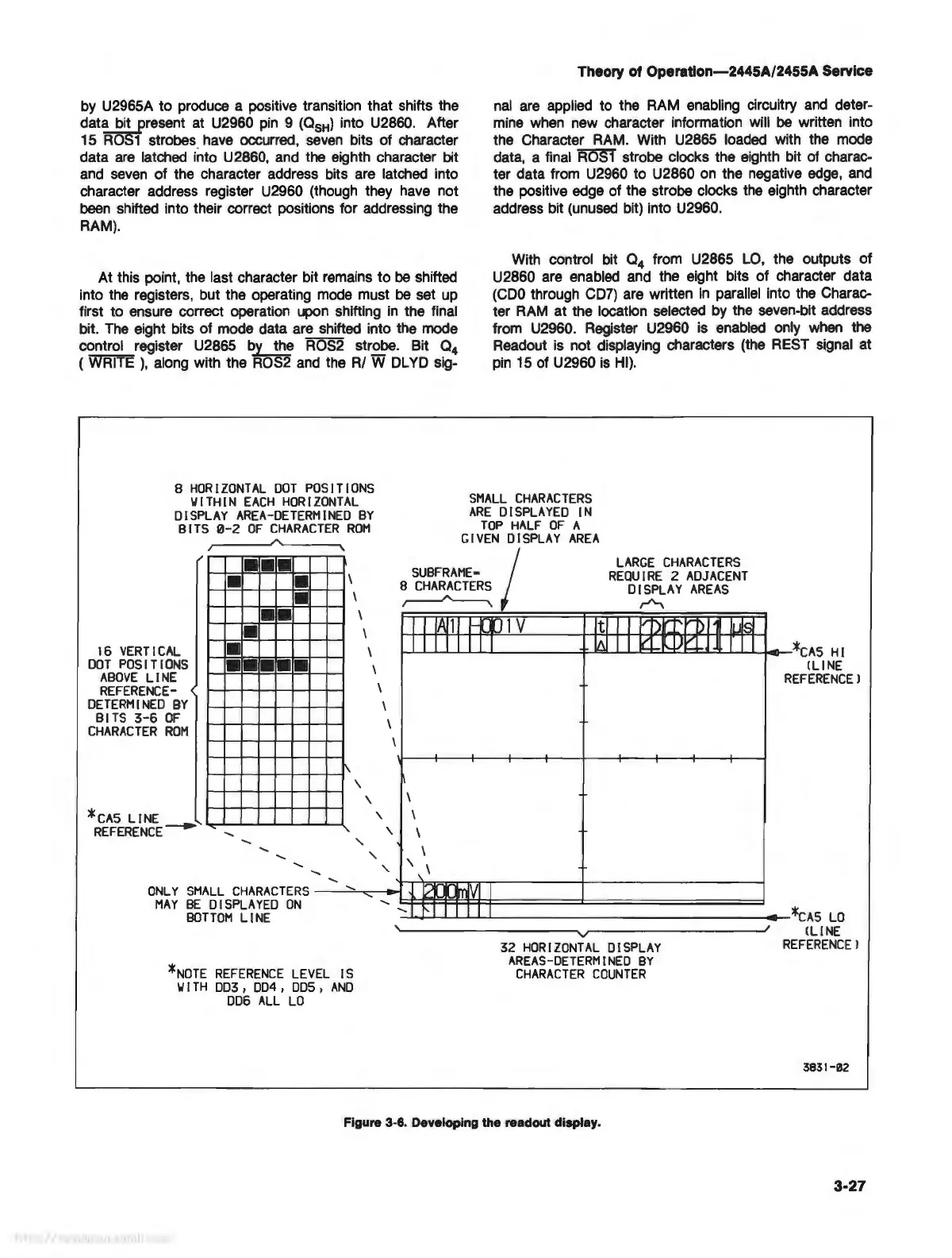
HORIZONTAL
DOT
POSITIONS
WITHIN
EACH
HORIZONTAL
DISPLAY
AREA-DETERMINED
BY
BITS
0-2
OF
CHARACTER
ROM
Theory
of
Operation-2445A/2455A Service
nal
are
applied to the RAM enabling circuitry
and
deter-
mine
when
new character information will
be
written into
the Character
RAM
. With U2865 loaded with the mode
data, a final
ROS1 strob
strobe clocks the eighth bit of charac-
ter data from U2960 to U2860
on
the negative
edge,
and
the positive edge of the strobe clocks
the
eighth character
address bit
(unused
bit) into U2960.
With control bit
0
4
from U2865
LO,
the outputs of
U2860 are enabled
and
the eight bits of character data
(CD0
through
CD7)
are written
in
parallel into the Charac-
ter
RAM
at the location selected
by
the seven-bit address
from U2960. Register U2960 is enabled only
when
the
Readout
is
not displaying characters (the
REST
signal at
pin
15 of U2960
is
HI).
SMALL
CHARACTERS
ARE
DISPLAYED
IN
TOP
HALF
OF
A
GIVEN
DISPLAY
AREA
•
•
•
• •
\
SUBFRAME•
8
CHARACTERS
I
LARGE
CHARACTERS
REQUIRE
2
ADJACENT
DISPLAY
AREAS
,.-1',
16
VERTICAL
DOT
POSITIONS
ABOVE
LINE
REFERENCE-
DETERMINED
BY
BITS
3-6
OF
CHARACTER
ROM
*cAS
LINE
REFERENCE
•
•
• •
•
•
•
•
-
•
\
\
\
\
1 V
4..IQ.I....LJU:::b..l:~~li_Li...L.l---*cAS
HI
\
\
CLINE
REFERENCE!
ONLY
SMALL
CHARACTERS
-
----'':::......,.----<-i
MAY
BE
DI
SPLAYED
ON
t::::t::=f=e!!::!=t=:l=====:t==========
BOTTOM
LINE
--'-..J-J......L.L....J.....L...JL-
_______________
*cAS
LO
*NOTE
REFERENCE
LEVEL
IS
WITH
003,
004,
DDS,
AND
006
ALL
LO
32
HORIZONTAL
DISPLAY
AREAS-DETERMINED
BY
CHARACTER
COUNTER
Figure 3-6. Developing the readout display.
CLINE
REFERENCE!
3831-02
3-27