Performance Tests
CSA7404B, TDS7704B, TDS7404B, TDS7254B & TDS7154B Service Manual
4-71
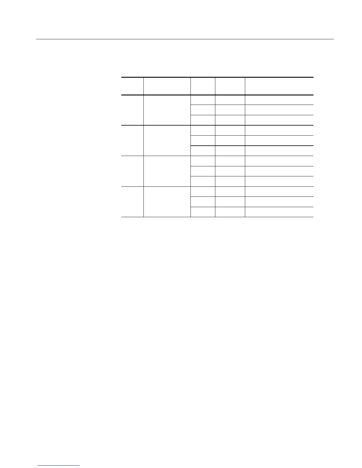
Table 4- 5: Offset accuracy (Cont.)
Scale
setting
Accuracy limits
Generator
setting
Offset
setting
1
Position setting
(Divs)
50 mV 0 +0.5 V +500 mV +491.00 mV t o +509.00 mV
0V 0. 0 mV --6.50 mV to +6.50 mV
-- 0 . 5 V --500 mV --509. 00 mV to --491.00 mV
100 mV 0 +5 V +5.0 V +4.95 V to +5.05 V
0V 0. 0 V -- 2 5 m V t o + 2 5 m V
-- 5 V -- 5 . 0 V --5.05 V to --4.95 V
500 mV 0 +5 V +5.0 V +4.91 V to +5.09 V
0V 0. 0 V -- 6 5 m V t o + 6 5 m V
-- 5 V -- 5 . 0 V --5.09 V to --4.91 V
1V 0 +2.5 V +2.5 V +2.3725 V to +2.6275 V
0V 0. 0 V --115mVto+115mV
-- 2 . 5 V -- 2 . 5 V --2.6275 V to --2.3725 V
1
Set as precisel y as the instrument’s offset resolution permits.
d. Display the test signal:
H From the tool bar touch VERT and then touch Position.
H Use the keypad to set vertical position to 0.0 divisions (press CLR
and then ENTER, on the keypad).
H Touch Offset.
H Use the keypad to set vertical offset to the positive-polarity setting
listed in the table for the current vertical scale setting. The baseline
level may move off screen.
H Set the generator to the level and polarity indicated in the table for
the vertical scale, position, and offset settings you have made. The
DC test level should appear on screen. (If it doesn’t return, the offset
accuracy check has failed for the current vertical scale setting of the
current channel).
e. Measure the test signal: Press Close. Read the measurement results at
the Mean measurement readout. See Figure 4--12.
 Loading...


