Performance Tests
CSA7404B, TDS7704B, TDS7404B, TDS7254B & TDS7154B Service Manual
4-117
o. Verify that the instrument triggers at the 0 in the input signal (see
Figure 4--36). Enter pass or fail in the test record.
p. Touch the Clear button.
q. Enter data into Serial Pattern Data field for the next setting in Table 4--10
that is not yet checked.
r. Touch Apply.
s. Verify that the instrument triggers one Unit Interval (UI) after the 0 in
the input signal (see Figure 4--36). Enter pass or fail in the test record.
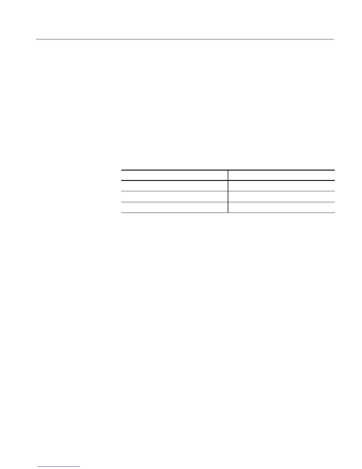
Table 4- 11: Word recognizer data
Serial pattern data Trigger location
4924 9249 2492 4924
16
One UI before the 1
9249 2492 4924 9249
16
At the 1
2492 4924 9249 2492
16
One UI after the 1
3. Verify that the serial path and pattern matching circuits can do isolated 1s:
a. Adjust the trigger LEVEL to trigger at 75% (+1 division) on the sine
wave.
b. Touch the Clear button.
c. Enter data into the Serial Pattern Data field for one of the settings in
Table 4--11 that is not yet checked. (Start with the first setting listed.)
d. Touch Apply.
e. Verify that the instrument triggers one Unit Interval (UI) before the 1 in
the input signal (see Figure 4--37). Enter pass or fail in the test record.
f. Touch the Clear button.
g. Enter data into the Serial Pattern Data field for the next setting in
Table 4--11 that is not yet checked.
h. Touch Apply.
i. Verify that the instrument triggers at the 1 in the input signal (see
Figure 4--37). Enter pass or fail in the test record.
j. Touch the Clear button.
k. Enter data into the Serial Pattern Data field for the next setting in
Table 4--11 that is not yet checked.
 Loading...


