Performance Tests
4-96
CSA7404B, TDS7704B, TDS7404B, TDS7254B & TDS7154B Service Manual
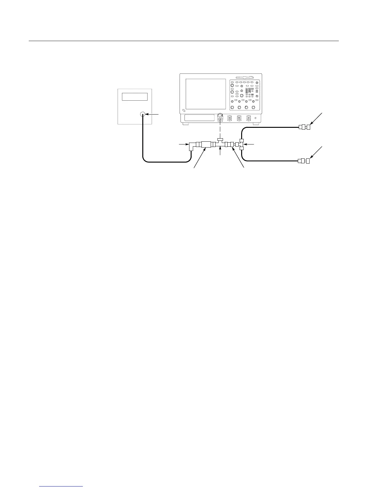
Instrument under test
Pulse
generator
50 Ω Cable
Output
20I 50 Ω Cable
20I 50 Ω Cable
SMA
short
SMA
short
BNC T
connector
2X Attenuator
BNC 90° female
to male adapter
SMA T
connector
BNC to SMA
adapter
Figure 4- 24: Delta time accuracy test hookup
1. Install the test hookup and preset the instrument controls:
a. Initialize the instrument: Press the DEFAULT SETUP button.
b. Hook up the pulse generator (see Figure 4--24 on page 4--96):
H Connect the pulse generator output to a 50 Ω precision coaxial cable
followedbya90° right-angle female to male BNC adapter, then a
50 Ω 2X attenuator. The attenuator is connected to one side of the
female BNC T connector. The other side of the BNC T is connected
to BNC male to SMA adapter. The SMA side is connected to the
male side of the SMA T connector. (Keep the distance between the
BNC T and S MA T as short as possible). Connect 20 inch 50 Ω
coaxial cables to each female side of the SMA T connector. Connect
the SMA short, to the remaining female SMA connector. Now
connect the male BNC T connector to CH 1.
H Set the pulse generator output for a positive-going pulse with a
rise-time as shown in Table 4--9 on page 4--98 for your instrument,
and for the fastest possible rep rate (at least 1 kHz).
H Verify that the measured fall--time of the pulse meets the fall--time
requirement shown in Table 4--9 on page 4--98.
H Set the pulse generator output for about 500 mV. (This amplitude
can be adjusted later to get a 6-division pulse on screen.)
c. Modify the initialized front-panel control settings:
H Power on the pulse generator.

 Loading...


