Performance Tests
CSA7404B, TDS7704B, TDS7404B, TDS7254B & TDS7154B Service Manual
4- 121
Equipment
required
One precision 50 Ω coaxial cables (Item 4)
One sine-wave generator (Item 12)
One SMA-to-BNC, TCA-BNC, or TCA-SMA adapters (Item 19)
Prerequisites See page 4--17. Also, the instrument must have passed Check DC
Voltage Measurement Accuracy on page 4--45.
1. Install the test hookup and preset the instrument controls:
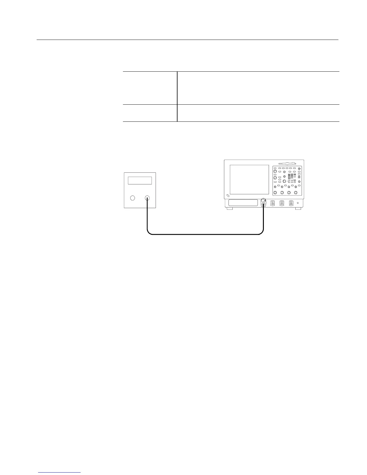
50 Ω Coaxial cables
Sine-wave
generator
Instrument under test
Figure 4- 39: Initial test hookup
a. Hook up test-signal source 1 (See Figure 4--39):
H Connect the sine wave output of the sine-wave generator through a
50 Ω precision coaxial cable to CH 1 through an adapter.
H Set the sine-wave generator to output a 1.5625 GHz sine wave.
b. Initialize the instrument: Press the DE FAULT SETUP button.
c. Modify the initialized front-panel control settings:
H Press the Vertical SCALE to 50 mV per division.
H Set the horizontal SCALE to 200 ps per division.
H From the button bar, touch the Disp (display) button.
H Set the Display Style to Dots.
H Set the Display Persistence to Variab le, and set the Persist Time to
3.0 s.
H Touch the Close button.
Check Serial Trigger Clock
Recovery Range
 Loading...


