Performance Tests
CSA7404B, TDS7704B, TDS7404B, TDS7254B & TDS7154B Service Manual
4-93
H Enter the count on the test record.
3. Confirm reference is within limits for logic levels:
a. Display the test signal:
H Move the cable from the timer-counter to the CH 1 input through an
adapter.
H Set the Vertical SCAL E to 1 V.
H Use the Vertical POSITION knob to center the display on screen.
b. Measur e logic levels:
H From the button bar, touch MEAS and select the Ampl tab.
H Touch the High and Low buttons.
H Touch the Close button.
c. Check REF OUT output against limits: CHECK that the CH 1 High
readout is ≥1.0 volt and that the CH 1 Low readout ≤0.25 volts.
4. Disconnect the hookup: Disconnect the cable and adapter from the instru-
ment.
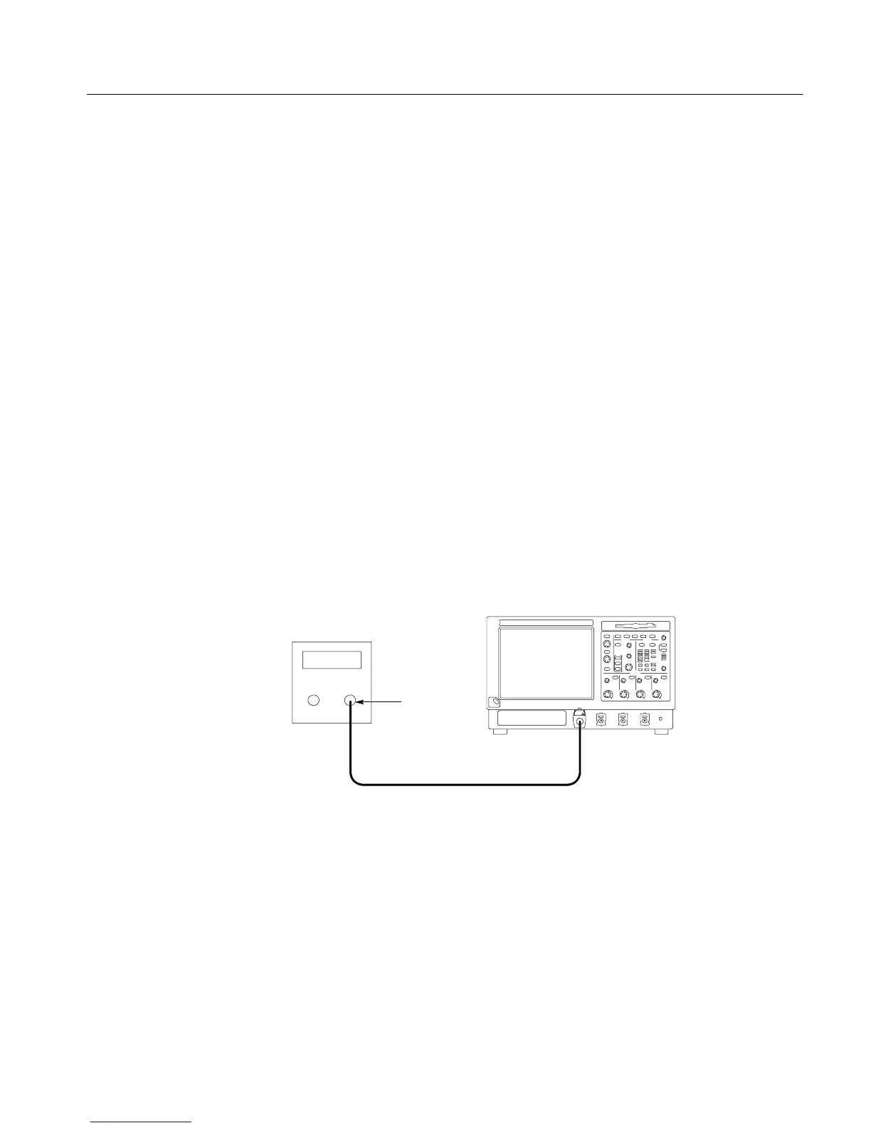
Instrument under test
50 Ω Coaxial cable
Output
Sine-wave
generator
Figure 4- 22: Initial test hookup
5. Install the test hookup and preset the instrument controls:
a. Initialize the instrument: Press the DEFAULT SETUP button.
b. Hook up the test-signal source: Connect, through a 50 Ω precision
coaxial cable, the output of the sine wave generator to CH 1 input
through an adapter (see Figure 4--22).
H From the button bar, touch MEAS and select the Ampl tab.
 Loading...


