Performance Tests
4-110
CSA7404B, TDS7704B, TDS7404B, TDS7254B & TDS7154B Service Manual
5. Disconnect the hookup: Disconnect the cables and adapters from the inputs
and outputs.
Equipment
required
Two dual-banana connectors (Item 5)
One BNC T connector (Item 6)
Two precision 50 Ω coaxial cables (I tem 4)
One DC calibrat ion generator (Item 9)
One SMA-to-BNC adapter (Item 19)
Prerequisites See page 4--17. Also, the instrument must have passed Check
Accuracy For Long-Term Sample Rate and Delay Time Accuracy and
Reference on page 4--92.
1. Install the test hookup and preset the instrument controls:
a. Hook up test-signal:
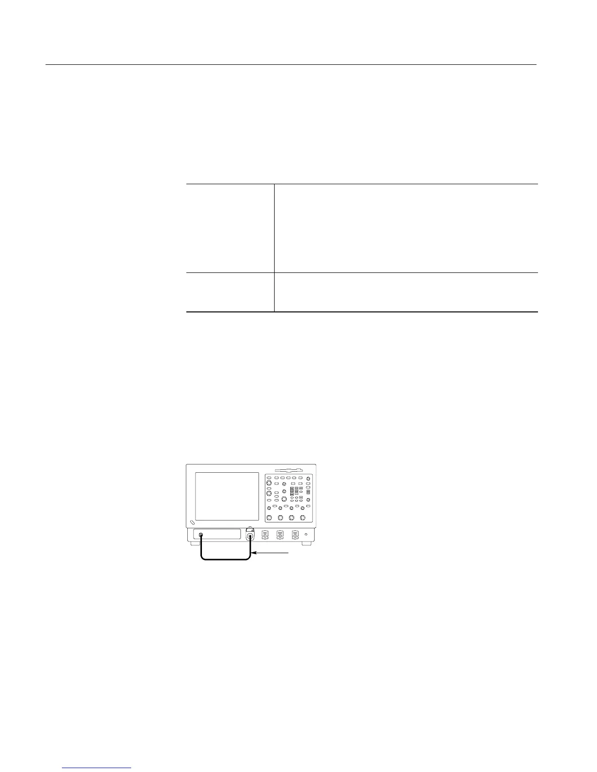
H Connect one of the 50 Ω cables to CH 1 through an adapter. See
Figure 4--31.
H Connect the other end of the cable just installed to the PROBE
COMPENSATION output. See Figure 4--31.
BNC cable from PROBE
COMPENSATION output to
CH 1 input
Instrument under test
Figure 4- 31: Initial test hookup
b. Initialize the instrument: Press the DE FAULT SETUP button.
c. Modify the initialized front-panel control settings:
H Set the Vertical SCALE to 100 mV.
Check Probe
Compensation Output
 Loading...


