Performance Tests
CSA7404B, TDS7704B, TDS7404B, TDS7254B & TDS7154B Service Manual
4- 129
Equipment
required
Two 62.5 m multimode fiber-optic cables (Item 34)
SMA cable (Item 21)
CW laser source (I tem 29)
Multimode optical attenuator (Item 30)
Optical power meter (It em 31)
O/E-to-SMA adapt er (It em 33)
TCA-SMA adapter (item 19)
Prerequisites See page 4--17. Also, the instrument must have passed Check DC
Voltage Measurement Accuracy on page 4--45.
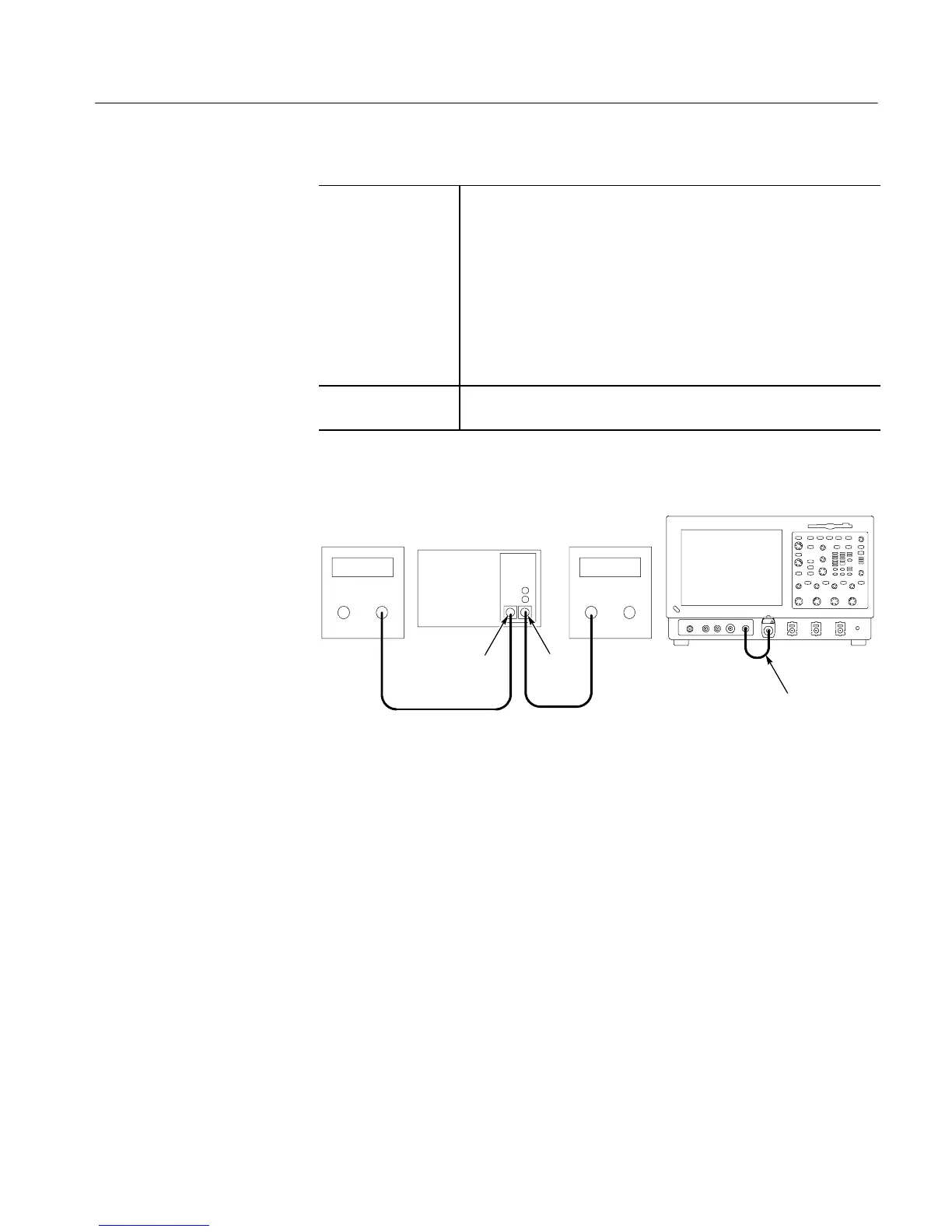
1. Install the test hookup and preset the instrument controls:
62.5 m Multimode
fiber-optic cables
CW laser
source
Optical power
meter
Multimode optical
attenuator
Optical
output
Optical
Input
O/E-to-SMA adapter,
SMA cable, and
TCA-SMA adapter
CSA7000B Instrument
Figure 4- 43: Initial test hookup
a. Hook up test-signal source 1 (See Figure 4--43):
H Connect the O/E Electrical Output to the CH 1 Input using an
O/E-to-SMA adapter, SMA cable, and TCA-SMA adapter.
H Connect the output of a CW laser source through a multimode
optical-fiber cable to the optical input of a multimode optical
attenuator.
H Connect the output of the optical attenuator to the input of the
optical power meter.
H Set the CW laser source to 780 nm.
H Set the multimode optical attenuator for 0.1 mW (--10 dBm) into the
optical power meter.
Check
Optical-to-Electrical Gain
 Loading...


