Performance Tests
4-84
CSA7404B, TDS7704B, TDS7404B, TDS7254B & TDS7154B Service Manual
H Display the reference waveforms. To do this, touch the Ref 3
Display Off button to toggle it to On and display the reference.
Select the Ref 2 tab and touch the Display Off button to toggle it to
On. You may notice their overlapping waveform handle icons. See
Figure 4--18 on page 4-- 84.
f. Measure the test signal:
H Locate the time reference points for these waveforms. Do this by
first identifying the point where the rising edge of the left-most
waveform crosses the center horizontal graticule line. Next, note the
corresponding time reference point for the right-most waveform. See
Figure 4--18 on page 4-- 84.
H Press CURSORS and select the V Bars Cursors Type.
H Touch the Close button.
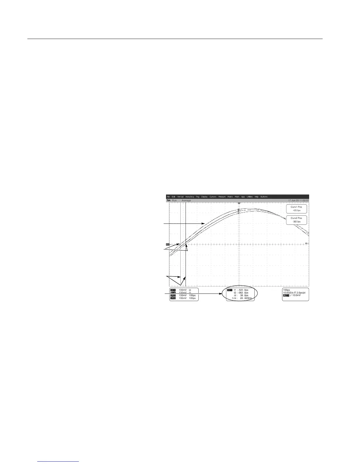
Locate the time
reference points for
these waveforms
2
Display the waveforms
1
Read results
4
Align each cursor to the
time reference points
3
Figure 4- 18: Measurement of channel delay
g. Check against limits: Use the cursors to measure the skew from CH 1 to
CH2,CH1toCH3,andCH1toCH4.Writedownthesethree
numbers in the first measurement column of Table 4--8. Note that these
numbers may be either positive or negative.
h. Move the power divider on CH 1 to CH 2. Move the power divider on
CH4toCH1.
 Loading...


