Performance Tests
4-76
CSA7404B, TDS7704B, TDS7404B, TDS7254B & TDS7154B Service Manual
NOTE. When setting the Fluke 9500B to output more than 5 V, use the following
procedure:
Press the Aux button
Press the fourth soft key down (Selects the pulse with an exclamation point)
Set the amplitude to 6.5 V or 10 V
Press the ->| key to select the pulse ener gy
Set the energy to 50J
Press the Output On key
Press the Trig Pulse soft key to trigger the pulse (this will generate a pulse with
59.172, 30.864, and 25 seconds duration respectively).
Use the normal DC output for the 1 V, 3 V, and 5 V generator settings.
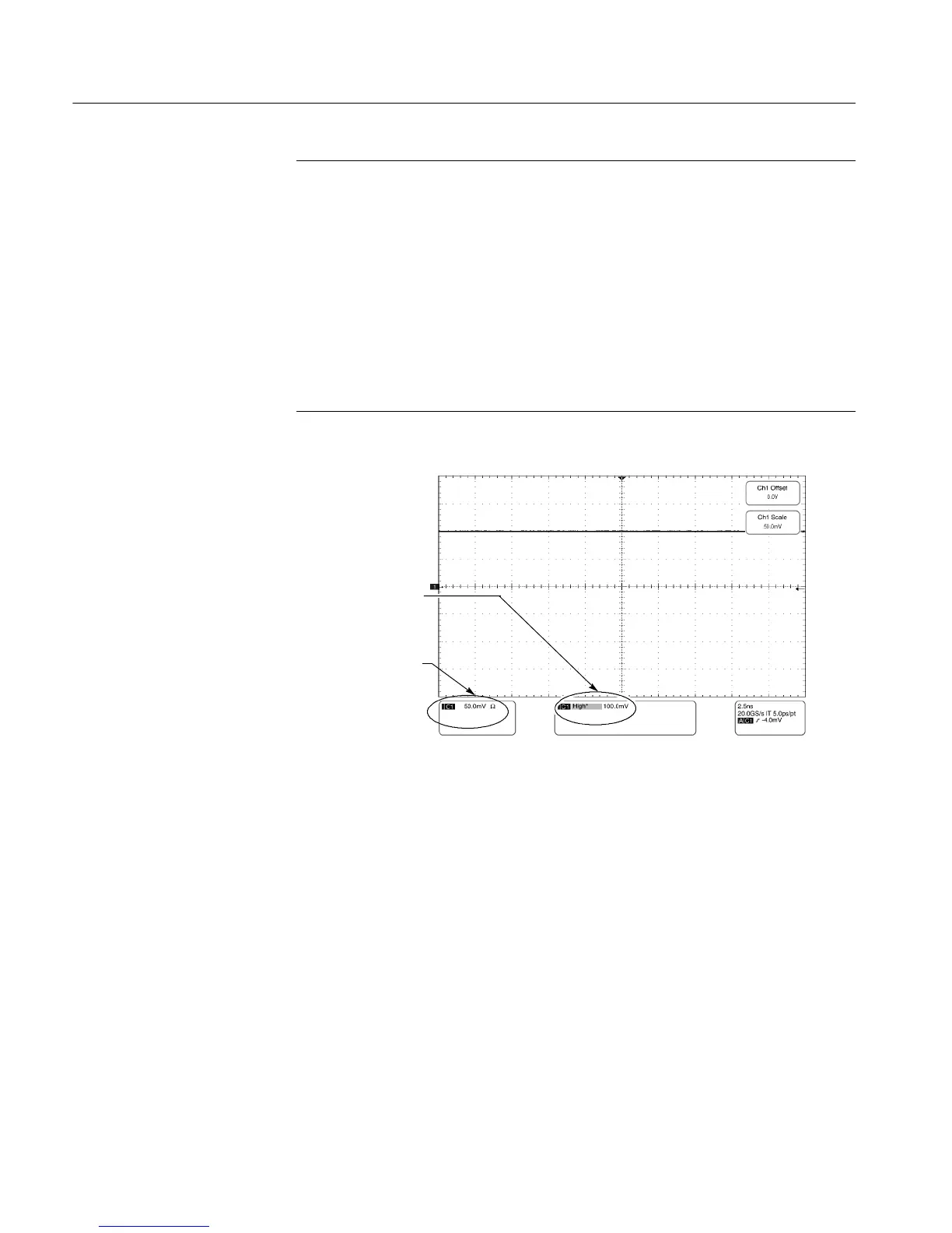
Turn on the
measurement called
high and read the
results here
After removing the
10X attenuator, check
the coupling readout
of the channel you are
testing
Figure 4- 14: Check of maximum input voltage
e. Check an unchecked generator setting against limits:
H Remove the 10X attenuator.
H CHECK that the coupling readout on screen for the selected channel
is as listed for the current vertical scale and position/offset/generator
settings. Enter result on test record.
H Reinstall the 10X attenuator.
f. Check the next generator setting: Repeat substeps d and e, using the new
generator setting as is listed in the table.
g. Check the remaining vertical scale settings: Repeat substeps c through f
until all vertical scale settings, listed in Table 4--6, are checked for the
channel under test.
 Loading...


