Home
Tektronix
Measuring Instruments
CSA7404B
Tektronix CSA7404B Service Manual
4
of 1
of 1 rating
348 pages
Give review
Manual
Specs
To Next Page
To Next Page
To Previous Page
To Previous Page
Loading...
Perfo
rman
ce
T
es
ts
4
-
120
CSA7404B
,
TDS
7704B,
TDS7404B,
TDS7254B
&
TDS7154B
S
ervic
e
Manua
l
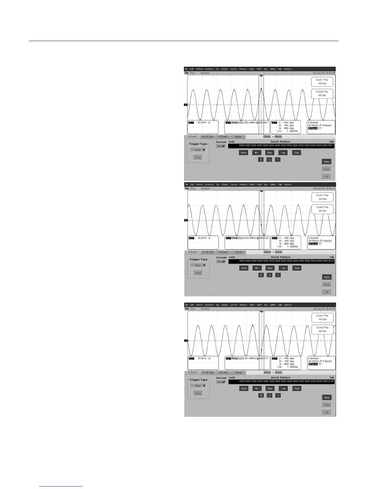
Triggering
2
clock
cycles
a
f
t
e
r
a1
.S
t
e
p3
,6
,9
,1
2
,...
Triggering
on
a
1.
Step
1,
4,
7
,1
0
,...
Triggering
1
clock
cycle
after
a1
.S
t
e
p2
,5
,8
,1
1
,...
Figure
4
-
38:
N
modulo
3
tr
iggering
195
197
Table of Contents
Table of Contents
5
Service Manual
1
List of Tables
12
Default Chapter
15
General Safety Summary
15
Service Safety Summary
17
Environmental Considerations
19
Manual Conventions
21
Manual Structure
21
Preface
21
Related Documentation
22
Specifications
23
Product and Feature Description
26
Acquisition Features
26
Table 1- 1: Instrument Models
26
Display Features
27
Measurement Features
27
Trigger Features
28
Convenience Features
28
Specification Tables
29
Table 1- 2: Channel Input and Vertical Specifications
29
Table 1- 3: Horizontal and Acquisition System Specifications
35
Table 1- 4: Trigger Specifications
39
Table 1- 5: Serial Trigger Specifications (Optional on TDS7000B Series)
43
Table 1- 6: Display Specifications
43
Table 1- 7: Input/Output Port Specifications
44
Table 1- 8: O/E Converter (CSA7000B Series Only)
47
Table 1- 9: Data Storage Specifications
49
Table 1- 10: Power Source Specifications
49
Table 1- 11: Mechanical Specifications
50
Table 1- 12: Environmental Specifications
51
Certifications and Compliances
52
Operating Information
55
Installation
57
Before You Start
57
Connect the Peripherals
57
Environmental Considerations 2
57
Table 2- 1: Additional Accessory Connection Information
58
Figure 2- 1: Locations of Peripheral Connectors on Rear Panel
59
Power on the Instrument
60
Figure 2- 2: Line Fuse and Power Cord Connector Locations, Rear Panel
60
Table 2- 2: Line Fuses
60
Powering off the Instrument
61
Software Installation
61
Figure 2- 3: On/Standby Switch Location
61
Operating Information
63
Back up User Files
63
User Interface Map
63
Front Panel Controls Map
65
Front Panel I/O Map
66
Instrument Diagnostics
67
Signal Path Compensation
67
Using the Online Help
67
Theory of Operation
69
Logic Conventions
71
Module Overviews
71
Input Signal Path
71
Display Panel
72
Front Panel
72
Rear Panel
73
Low Voltage Power Supply
73
Fans
73
Performance Verification 4
75
Performance Verification
77
Conventions
78
Figure 4- -1: Toolbar and Menu Bar
79
Brief Procedures
81
Self Tests
81
Functional Tests
82
Verify All Input Channels
83
Figure 4- 2: Universal Test Hookup for Functional Tests - CH 1 Shown
84
Figure 4- 3: Channel Button Location
85
Table 4- 1: Vertical Settings
85
Verify the Time Base
86
Figure 4- 4: Setup for Time Base Test
87
Verify the a (Main) and B (Delayed) Trigger Systems
88
Figure 4- 5: Setup for Trigger Test
89
Verify the File System
90
Figure 4- 6: Setup for the File System Test
90
Performance Tests
93
Prerequisites
93
Equipment Required
94
Table 4- 2: Test Equipment
94
CSA7000B & TDS7000B Test Record
97
Signal Acquisition System Checks
121
Check DC Voltage Measurement Accuracy
121
Figure 4- 7: Initial Test Hookup
122
Table 4- 3: DC Voltage Measurement Accuracy
123
Figure 4- 8: Measurement of DC Accuracy at Maximum Offset and Position
124
Check DC Gain Accuracy
125
Figure 4- 9: Initial Test Hookup
126
Table 4- 4: Gain Accuracy
127
Figure 4- 10: Measurement of DC Gain Accuracy
143
Check Offset Accuracy
144
Figure 4- 11: Initial Test Hookup
145
Table 4- 5: Offset Accuracy
146
Figure 4- 12: Measurement of Offset Accuracy
148
Figure 4- 13: Initial Test Hookup
150
Table 4- 6: Maximum Input Voltage Limit
151
Figure 4- 14: Check of Maximum Input Voltage
152
Check Analog Bandwidth
153
Figure 4- 15: Initial Test Hookup
154
Table 4- 7: Analog Bandwidth
155
Figure 4- 16: Measurement of Analog Bandwidth
156
Check Delay between Channels
158
Figure 4- 17: Initial Test Hookup
159
Figure 4- 18: Measurement of Channel Delay
160
Table 4- 8: Delay between Channels Worksheet
161
Check Channel Isolation (Crosstalk)
162
Figure 4- 19: Initial Test Hookup
162
Check Input Impedance
166
Figure 4- 20: Initial Test Hookup
167
Time Base System Checks
168
Figure 4- 21: Initial Test Hookup
168
Figure 4- 22: Initial Test Hookup
169
Figure 4- 23: Final Test Hookup
170
Check Delta Time Measurement Accuracy
171
Figure 4- 24: Delta Time Accuracy Test Hookup
172
Table 4- 9: Delta Time Measurement
174
Trigger System Checks
175
Figure 4- 25: Initial Test Hookup
175
Figure 4- 26: Measurement of Time Accuracy for Pulse and Glitch Triggering
176
Check Sensitivity, Edge Trigger, DC Coupled
177
Figure 4- 27: Initial Test Hookup
178
Figure 4- -28: Measurement of Trigger Sensitivity - - 50 Mhz
179
Output Signal Checks
182
Check Outputs — CH 3 Signal out and Aux Trigger out 4
183
Check Probe Compensation Output
186
Serial Trigger Checks (TDS7000B Series Option ST and CSA7000B Series Only)
190
Check Serial Trigger Baud Rate Limits and Word Recognizer Position
190
Accuracy
190
Table 4- 10: Serial Pattern Data
191
Table 4- 11: Word Recognizer Data
193
Check Serial Trigger Clock Recovery Range
197
Table 4- 12: Clock Recovery Input Frequencies and Baud Rates
199
Optical-To-Electrical Converter Checks (CSA7000B Series Only)
201
Check Dark Level Calibration
201
Table 4- 13: Dark Level
202
Check Maximum Optical-To-Electrical Noise 4
203
Table 4- 14: Optical Noise Limits
204
Check Optical-To-Electrical Gain 4
205
Table 4- 15: O/E Gain
206
Check Optical-To-Electrical System Bandwidth 4
207
Table 4- 16: O/E System Bandwidth
211
Sine Wave Generator Leveling Procedure
213
Adjustment Procedures
215
Adjustment Interval
217
Adjustment after Repair
217
Adjustment
217
Maintenance
219
Preventing ESD
221
Inspection and Cleaning
222
General Care
222
Cleaning Optical Connectors
222
Interior Cleaning
223
Exterior Cleaning
224
Flat Panel Display Cleaning
224
Table 6- 1: External Inspection Check List
224
Table 6- 2: Internal Inspection Check List
225
Removal and Installation Procedures 6
225
Removal and Installation Procedures
229
Preparation
229
Table 6- 3: Tools Required for Module Removal
230
Procedures for External Modules
231
Procedures for Modules
243
Troubleshooting
285
Service Level
285
Check for Common Problems
285
Equipment Required
287
Fault Isolation Procedure
287
BIOS Error Messages 6
287
Dip Switch Controls 6
291
PPC and Microatx PC Diagnostics
292
After Repair
295
Software Updates
295
BIOS Error Messages
296
BIOS Beep Codes
301
Dip Switch Controls
302
Diagnostic LED
303
Troubleshooting Using Reset Circuits
304
Update/Restore the Microatx Board CMOS
306
Installing an Authorization Key
307
Hard Disk Drive Maintenance
307
Repackaging Instructions
309
Packaging
309
Shipping to the Service Center
309
Options 7
311
Accessories 7
313
Symbols 9
325
Other manuals for Tektronix CSA7404B
User Manual
438 pages
4
Based on 1 rating
Ask a question
Give review
Questions and Answers:
Need help?
Do you have a question about the Tektronix CSA7404B and is the answer not in the manual?
Ask a question
Tektronix CSA7404B Specifications
General
Brand
Tektronix
Model
CSA7404B
Category
Measuring Instruments
Language
English
Related product manuals
Tektronix CSA7404
480 pages
Tektronix 492
303 pages
Tektronix 576
251 pages
Tektronix A622
28 pages
Tektronix P6015
26 pages
Tektronix Series
104 pages
Tektronix DMM830
42 pages
Tektronix DAS9100
29 pages
Tektronix RSA306B
8 pages
Tektronix WFM 8300
8 pages
Tektronix KEITHLEY 2450-EC
93 pages
Keithley SourceMeter 2410
125 pages