Performance Tests
4- 134
CSA7404B, TDS7704B, TDS7404B, TDS7254B & TDS7154B Service Manual
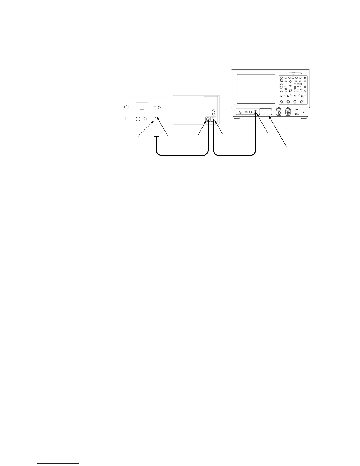
Optical impulser generator
Variable optical attenuator
OPTICAL
INPUT
OPTICAL
OUTPUT
OPTICAL
INPUT
Fiber-optic cableFiber-optic cable
OUTPUT
DIRECT
10dB Optical
attenuator
O/E Electrical
Out-to-CH1
input adapter
CSA7000B Instrument
Figure 4- 44: Optical bandwidth hookup
6. Select the Horizontal tab, do the following;
a. Set the Scale to 2.5 ns/div. (This setting will make it easier to initially
locate the optical pulse later in the procedure.)
b. Set the Position to 15.0%. (This setting will make it easier to locate the
first optical pulse later in the procedure.)
c. Set the Rec Length to 500. Verify that the sample rate is still set to
20 GS/s.
7. From the tool bar, touch Vert, do the the following:
a. Set the Scale to 20.0 W/div.
b. Set Position to -- 2 . 0 d i v .
c. Set the Calibrated Wavelength to 1550 nm.
8. Press the PUSH TO SET 50% button to set the trigger point midway on the
rising signal.
9. Decrease the amount of attenuation provided by the optical attenuator until a
pulse appears.
10. Adjust the attenuation of the variable optical attenuator until it produces an
impulse pulse amplitude of 80 W
p-p.
See Figure 4--45.

 Loading...


