Troubleshooting
6-70
CSA7404B, TDS7704B, TDS7404B, TDS7254B & TDS7154B Service Manual
Measure the power supply voltages with the voltmeter and compare each reading
to the values listed in the tables. If the voltages are within about 5% of the
nominal voltages, your power supply is functional.
Table 6- 5: Power supply voltages
Front power distribution board
(P2) and Power supply (J2)
Voltage
Rear power distribution board
(P1) and Power supply (J1)
Voltage
PinsA/B/C1,3,5,7,9,11 +3.3 V Pins A/B/C5, 6 +12 V
Pins A/B/C13 -- 1 5 V Pins A/B/C8, 9, 11, 12, 14, 15, 17 +5 V
Pins A/B/C15 +15 V Pins A/B/C19, 21, 23, 25, 27, 29, 31 +3.3 V
Pins A/B/C17, 18, 20, 21, 22 -- 5 V Pi ns B/C3 (fan voltage) +9.8 V
Pins A/B/C24, 25, 27, 28, 30, 31 +5 V
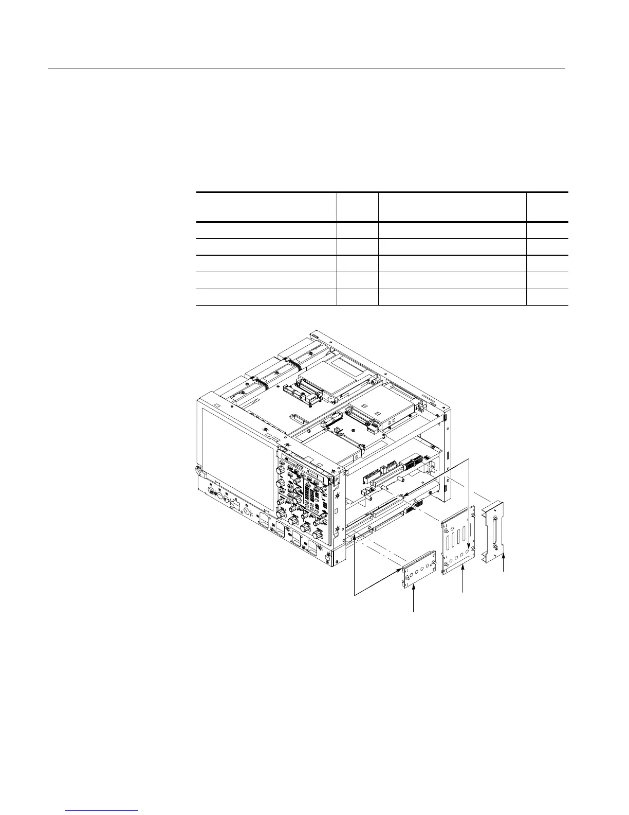
Rear power
distribution
circuit board
Front power
distribution
circuit board
PA bus
circuit board
J2 and P2
J1 and P1
Figure 6- 45: Connectors J1 and J2
If there is a display on the VGA port, but not on the LCD, replace the display
assembly (LCD, lamps, and cable).
If the Instrument Will Not
Boot

 Loading...


