MX32v2
ANALOG AND DIGITAL CONTROLLER
USER MANUAL
Revision D.0
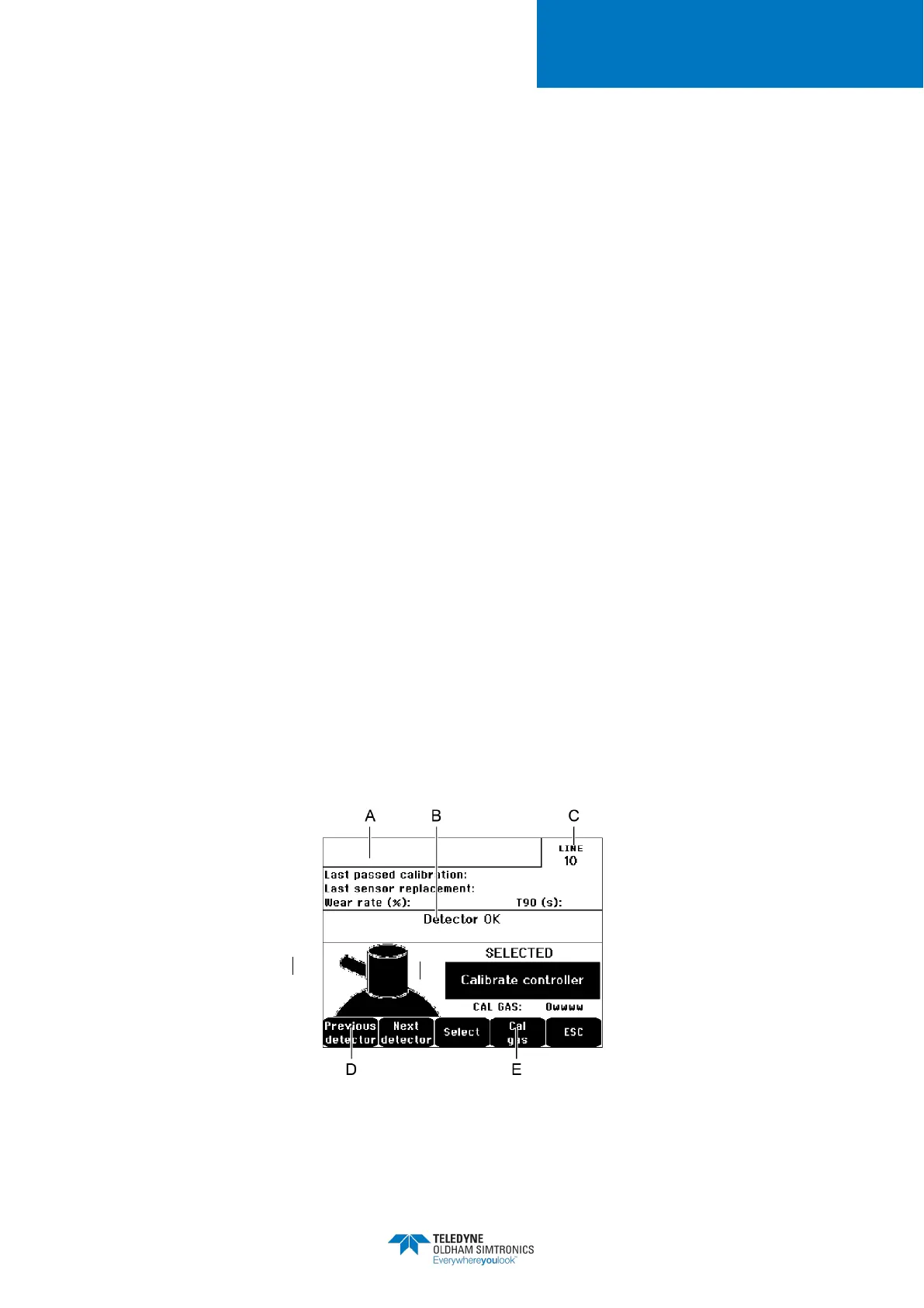
A. Display of information described by the
COM 32
application: i.e., measurement range,
gas detected, current detector ID and its type.
Display for the current detector:
• Last passed calibration
: Date and time of the last calibration carried out and
completed.
• Last sensor replacement
: Date and time of last cell change.
: Relation between the value of the standard gas and the value read
(sensitivity measurement). A wear rate in excess of 100% entails a sensor
replacement.
Display of the address (digital detector) or line number (analog detector) to which the
detector is connected.
D. Selecting the detectors to be calibrated:Select one or several detectors using the
or
keys.
• On pressing the
key, press
to enter its value by means of the ↑↓
keys. Validate by pressing
•
Note: Only analog detectors that are not equipped with
calibrated from the MX32v2 controller. For the other detectors, the menu “Sel.
Detector” only makes it possible to put them in calibration mode so that they
not activate alarms during their manual calibration.
• Press
to launch the procedure of recording the measurements on the
detectors to be calibrated. Proceed to paragraph “2 Recording”.
E. Display the calibration gas.
Figure 38: Example of the “Select detectors” screen