Section E – Autosampler Installation
CD14 Tester & CD AutoPlus Autosampler User Guide—75-108-800 Rev. B—31 May 2021 41 of 130
EAR99 technology subject to restrictions on cover page.
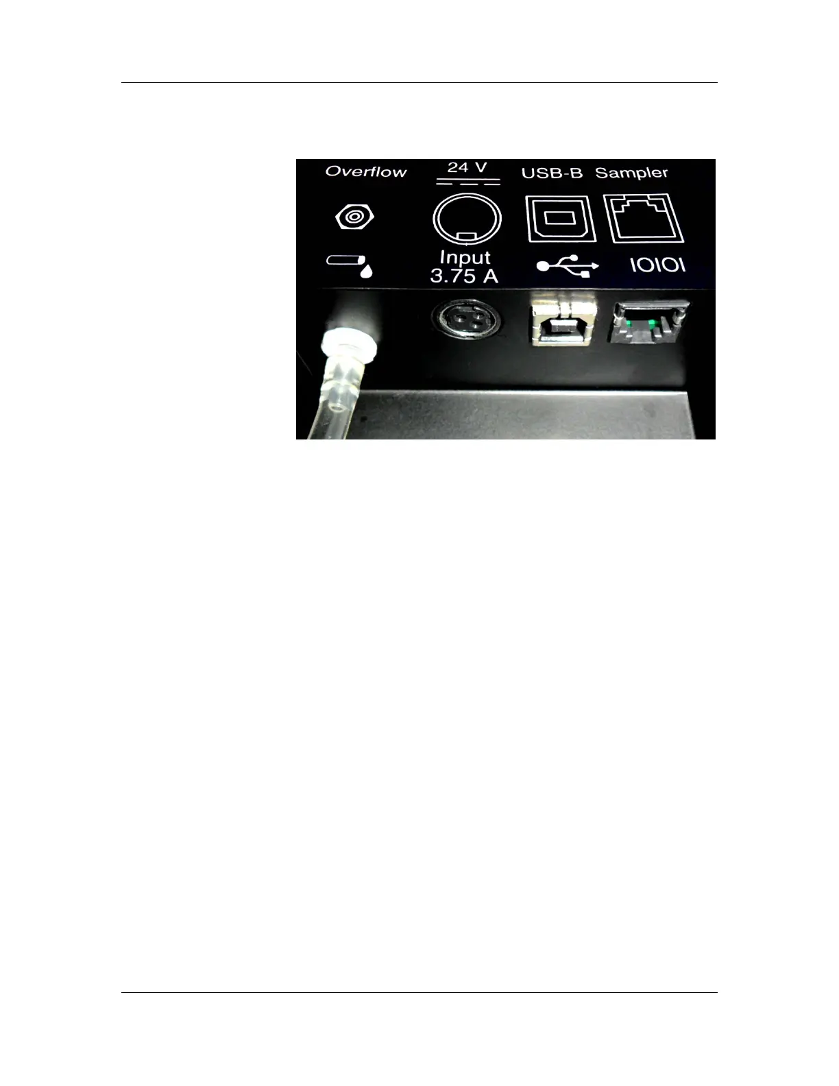
Figure E-2: AutoFill Back Panel and Ports
This section provides instructions on making the power
connections to the CD AutoPlus and AutoFill.
1. Ensure the power switch located on the right side of
the CD AutoPlus is in the off (O) position.
2. Connect the power supply to the port labeled 24 V
Input 3.75 A on the lower left corner of the back
panel of the CD AutoPlus, flat side facing the unit
(the connector is keyed so it will only fit one way).
Then connect the power supply to the wall outlet.
3. Ensure the power switch located on the back of the
AutoFill is in the off (O) position.
4. Connect the power supply to the port labeled 24 V
Input 3.75 A on the back of the AutoFill, flat side
facing the user (the connector is keyed so it will only
fit one way). Then connect the power supply to the
wall outlet.
5. Connect a flat RS-232 cable from the ‘Host’ port of
the CD AutoPlus on the left of the CD14 Tester to
the ‘Sampler A’ port of the CD14 Tester.
6. Connect a flat RS-232 cable from the ‘Host’ port of
the CD AutoPlus on the right of the CD14 Tester to
the ‘Sampler B’ port of the CD14 Tester.