BRAVO – Wireless Alarm Control Panel
30
Menu “6. Slots”
In this menu the installer sets the parameters of the
mounted communication modules to panel’s PCB.
Select the “6. Slots” menu. At the right side of the
screen are displayed parameters for setting.
ATTENTION: The mounted communication
modules to the BRAVO PCB must be enabled for
operation via the ProsTE programming software
or AjaxWEB!
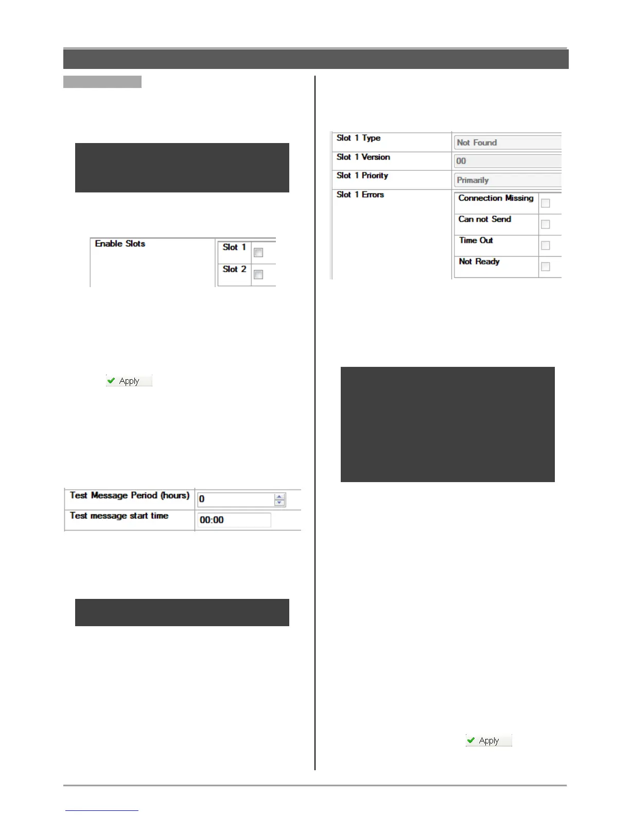
Enable Slots (enabling the communication
modules).
- Slot 1 - Corresponds to Slot 1 terminal on the
BRAVO’s PCB.
- Slot 2 - Corresponds to Slot 2 terminal on the
BRAVO’s PCB.
To enable the mounted to Slot 1 or 2 communication
module you have to select the field next to it.
Press the button.
To view information about the type of the
communication module you have first to write the new
configuration to the module and then to read it again.
Test Message Fields
In the fields the installer sets a start time for sending of
test message and a period in hours.
Test Message Period (hours) - Time (0-255) in
hours for periodical sending of test messages.
Test Message start time – Set a start time for
sending a test message.
ATTENTION: Sending of test messages can be
disabled if in the both fields is entered 0.
Information fields for the communication module
mounted to Slot 1 or 2.
The fields are locked for editing and can be only
reviewed by user.
- Slot 1 Type – Type of the communication module
connected to Slot 1 – GPRS, PSTN or other.
- Slot 1 Version – The software revision of the module.
- Slot 1 Priority – Priority for sending messages for
events. The priority depends on the setting of DIP-
switch 6*.
* When DIP-switch 6 is set on “OFF” position the
message transmitting is from alternative type: the
mounted to Slot 1 module starts sending
messages, and this mounted to Slot 2 is waiting.
If the module to Slot 1 fails, the module to Slot 2
starts sending the same message. If the module
to Slot 1 succeeds, the module to Slot 2 does not
transmit the message at all.
When DIP-switch 6 is set on “ON” position the
message is transmitted by the both modules.
- Slot 1 Errors – In the fields are viewed the current
existing faults and errors for the communication module
operation.
The existing errors are selected in the field next to them,
as the description is as follows:
- Connection Missing – Failure in connection
with the server for monitoring and management
of the system.
- Cannot Send – Event in the system (alarm or
trouble) that cannot be send because of failure
in the connection with server or other trouble.
- Time Out – Problem with the communication
module and lost connection with the panel.
- Not Ready – The communication module is
not ready for operation – no SIM card inserted
or the module is missing, but it is enabled for
operation.
The information field for Slot 2 includes identical
information.
Save the new configuration with button.
CONFIGURATION WITH ProsTE SOFTWARE