19
You can check the SSID and key of the CPE1 or CPE2 by choosing Wireless > Basic after logging in to the
web UI.
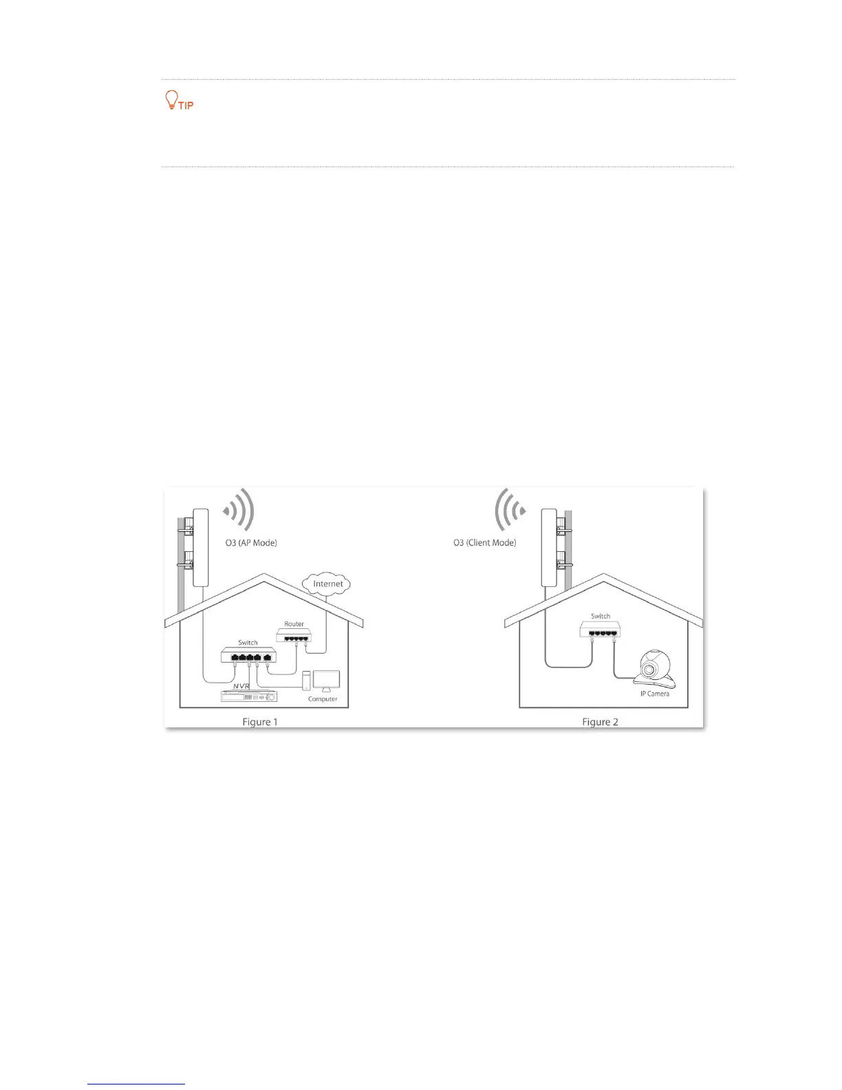
2.2.3 Installing the CPEs
The CPE (transmitter in AP mode) with LED1, LED2 and LED3 solid on should be connected to the switch
connecting to a network video recorder (NVR). See Figure 1 below.
The CPE (receiver in Client mode) with LED1, LED2 and LED3 blinking should be connected to the switch
connecting to a monitoring IP camera. See Figure 2 below.
Detailed procedures are as follows:
Step 1 Place the transmitter in the open air at the point where the NVR is located. Place the receiver in the
open air at the point where the IP camera is located.
Step 2 Uncover the housings of the two CPEs, and connect the PoE/LAN/WAN ports of the CPEs to PoE
injectors respectively. The LAN/WAN LED indicators light up.
Step 3 Adjust the two CPEs’ direction or location until the LED1, LED2 and LED3 of the two CPEs light up.
Step 4 Use the plastic straps to attach the two CPEs to the poles respectively.
----End
 Loading...