CPU 1 CPU 2
2cycledelay
2cycledelay
CCM-R4
CCM-R4
compare
CPU1CLK
CPU2CLK
compare
error
Input+Control
Output+Control
48
TMS570LS0714
SPNS226E –JUNE 2013–REVISED NOVEMBER 2016
www.ti.com
Submit Documentation Feedback
Product Folder Links: TMS570LS0714
System Information and Electrical Specifications Copyright © 2013–2016, Texas Instruments Incorporated
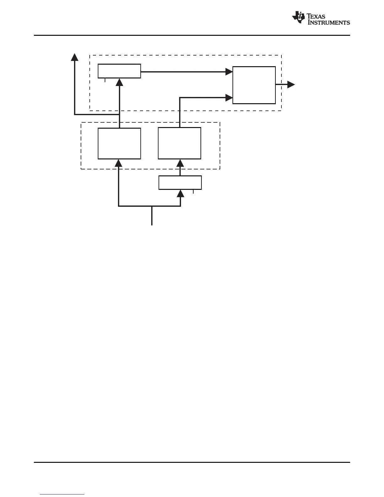
Figure 6-2. Dual Core Implementation
The CPUs have a diverse CPU placement given by following requirements:
• different orientation; for example, CPU1 = "north" orientation, CPU2 = "flip west" orientation
• dedicated guard ring for each CPU
Figure 6-3. Dual-CPU Orientation
6.5.4 Duplicate Clock Tree After GCLK
The CPU clock domain is split into two clock trees, one for each CPU, with the clock of the second CPU
running at the same frequency and in phase to the clock of CPU1. See Figure 6-2.
6.5.5 ARM Cortex-R4F CPU Compare Module (CCM) for Safety
This device has two ARM Cortex-R4F CPU cores, where the output signals of both CPUs are compared in
the CCM-R4 unit. To avoid common mode impacts the signals of the CPUs to be compared are delayed in
a different way as shown in Figure 6-2.
To avoid an erroneous CCM-R4 compare error, the application software must initialize the registers of
both CPUs before the registers are used, including function calls where the register values are pushed
onto the stack.
 Loading...


