BIAS_EN
Low-Power
Oscillator
LFEN
LF_TRIM
HFEN
HF_TRIM
LFLPO
HFLPO
HFLPO_VALID
nPORRST
52
TMS570LS0714
SPNS226E –JUNE 2013–REVISED NOVEMBER 2016
www.ti.com
Submit Documentation Feedback
Product Folder Links: TMS570LS0714
System Information and Electrical Specifications Copyright © 2013–2016, Texas Instruments Incorporated
6.6.1.1.1 Timing Requirements for Main Oscillator
Table 6-9. Timing Requirements for Main Oscillator
MIN NOM MAX UNIT
tc(OSC) Cycle time, OSCIN (when using a sine-wave input) 50 200 ns
tw(OSCIL)
Pulse duration, OSCIN low (when input to the OSCIN
is a square wave)
15 ns
tw(OSCIH)
Pulse duration, OSCIN high (when input to the OSCIN
is a square wave)
15 ns
6.6.1.2 Low-Power Oscillator
The Low-Power Oscillator (LPO) is comprised of two oscillators — HF LPO and LF LPO, in a single
macro.
6.6.1.2.1 Features
The main features of the LPO are:
• Supplies a clock at extremely low power for power-saving modes. This is connected as clock source 4
of the Global Clock Module (GCM).
• Supplies a high-frequency clock for non-timing-critical systems. This is connected as clock source 5 of
the GCM.
• Provides a comparison clock for the crystal oscillator failure detection circuit.
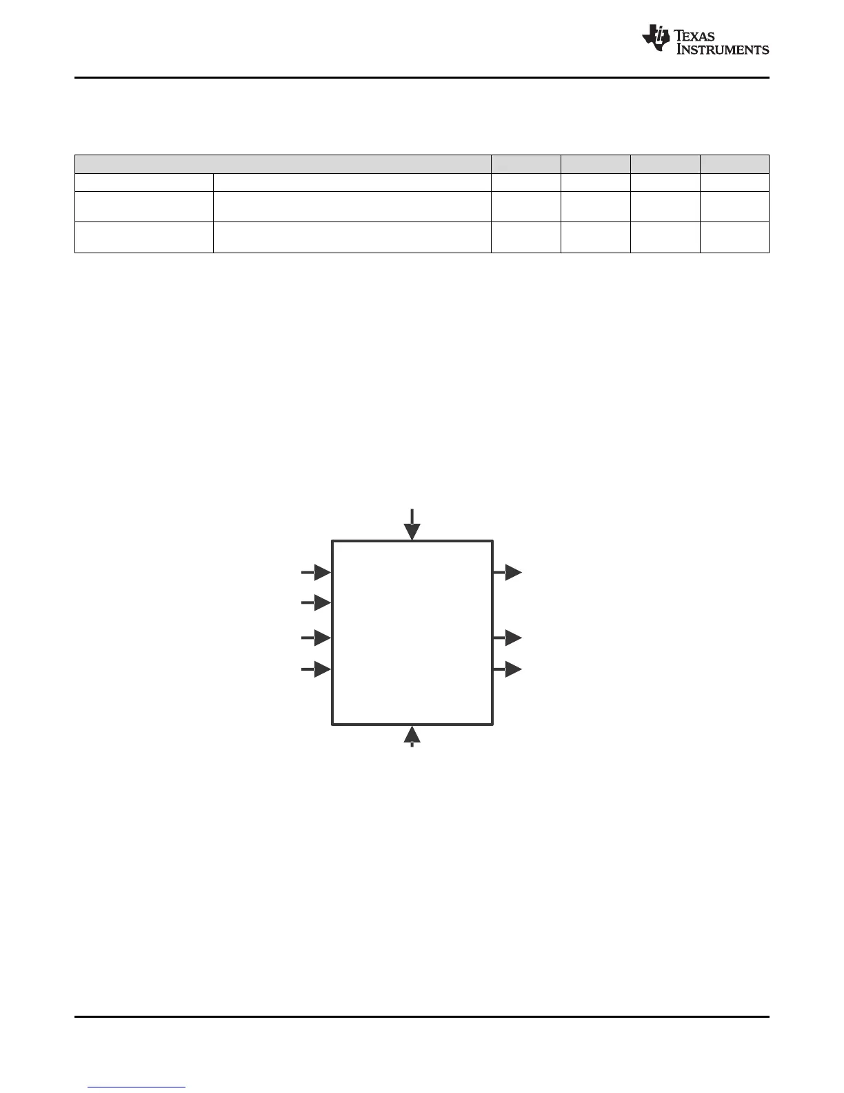
Figure 6-5. LPO Block Diagram
Figure 6-5 shows a block diagram of the internal reference oscillator. This is a low-power oscillator (LPO)
and provides two clock sources: one nominally 80 kHz and one nominally 10 MHz.
 Loading...


