Contents Page
1 Safety 1
2 Getting Started Quickly 3
2.1 Setup 3
2.2 Keyboard Summary 3
2.3 Display Arrangement 5
3 Description 6
3.1 Parts List – Accessories 7
3.2 Technical Data 8
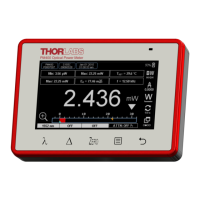
3.2.1 PM100 Display Unit 8
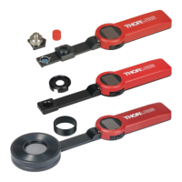
3.2.2 S120B / S121B Silicon Sensor (PM120 / PM121) 9
3.2.3 S122B Germanium Sensor (PM122) 10
3.2.4 S130A / S132B Slim Sensor (PM130 / PM132) 11
3.2.5 S140A / S144A Integrating Sphere Sensor (PM140 / PM144) 12
3.2.6 S210A 3W Thermal Sensor (PM210) 13
3.2.7 S212A 10W Thermal Sensor (PM212) 14
3.2.8 S213A 30W Thermal Sensor (PM213) 15
3.3 Physical Overview 16
3.4 Operating Instruction 17
3.4.1 Inserting and Charging the Battery Pack 17
3.4.2 Switching On and Off the Unit 18
3.4.3 Principal of Operation and Menu Navigation 18
3.4.4 Connecting a Photodiode Sensor (PM100 Series) 19
3.4.4.1 Dark current adjustment 20
3.4.4.2 Wavelength Correction 20
3.4.4.3 Attenuation/Gain Correction
21
3.4.5 Connecting a Thermal Sensor (PM200 series) 21
3.4.5.1 Zeroing the Sensor 22
3.4.5.2 Attenuation/Gain Correction 22
3.4.6 Range Setting 23
3.4.7 Relative Measurements 23
3.4.8 Zoom Functions 24
3.4.9 Representation of the Optical Power Reading 24
3.4.9.1 Power (Watts) and Bar-Graph Display 24
3.4.9.2 Digital Needle Display 25
3.4.9.3 Tune-Graph Display 26
3.4.9.4 Statistics Display 27
3.4.9.5 Power dBm Display 27